Section IV – Diagrams
MN06135 Issue/Rev. 1.3 (6/17) 10
Switch Settings
A new 8 pin DIP switch will be available for use (SW SW1-8). The switch will be utilized as follows:
SW1-1 force firmware upgrade (powers up waiting for firmware upgrade)
SW1-2 SW1-3
OFF OFF use programmed IP address
ON OFF use 192.168.0.1
OFF ON use 10.0.0.1
ON ON use DHCP
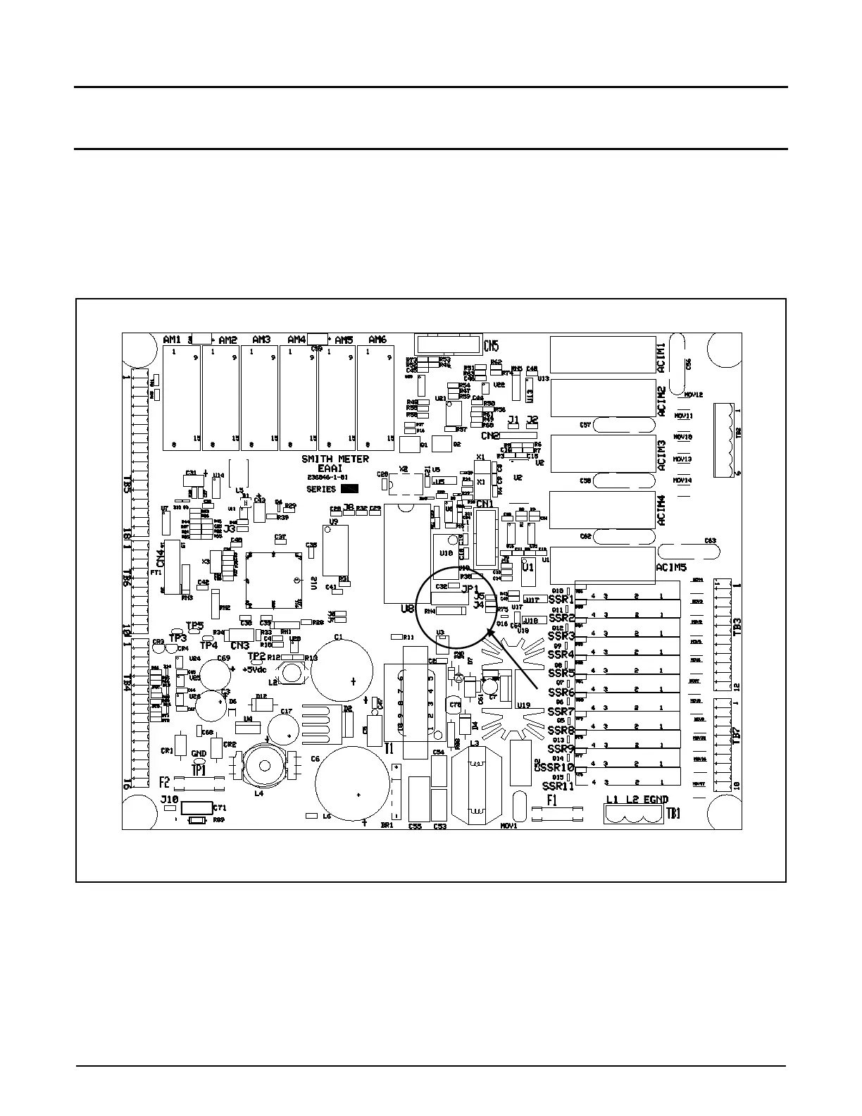
Figure 6. EAAI Layout
The user-configurable jumper on the EAAI board is indicated by a circle and arrow in the diagram above. See the
table on the following page for an explanation of analog module settings. This jumper has been configured for the
modules that were shipped with the unit. Changes should only be made if different modules are added or deleted.
Modules must be installed with inputs first, followed by outputs.