Section IV – Diagrams
MN06135 Issue/Rev. 1.3 (6/17) 39
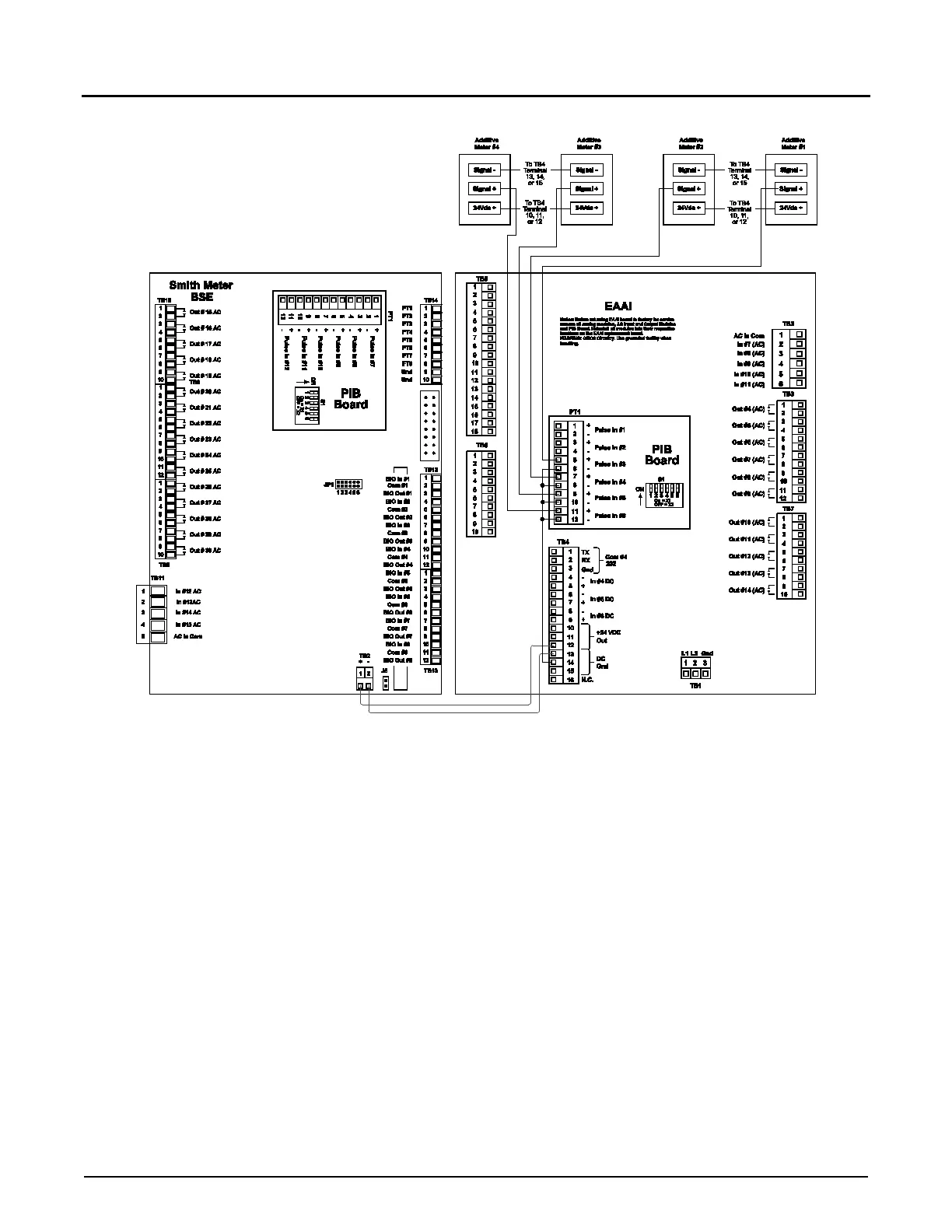
Figure 25. Wiring Diagram, Four Additive Meters
This diagram is valid only when using one or two product meters. For other setups refer to the table on
pulse inputs for available wiring connections.
Caution: For clarity, shields not shown. Connect shields to terminals 3, 13, 14, or 15 of Terminal Block 4.