Section IV – Diagrams
MN06135 Issue/Rev. 1.3 (6/17) 45
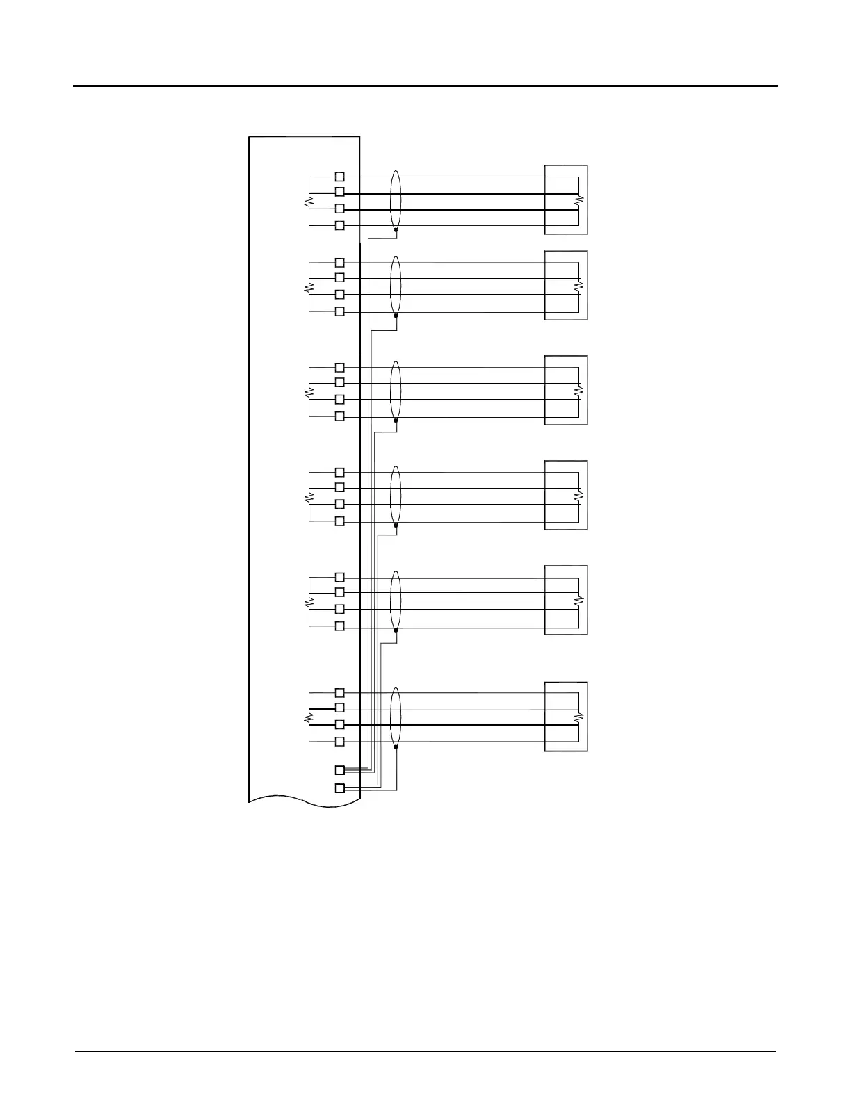
Figure 31. Resistance (RTD) Input
Note: If using two twisted pairs of wires, RTD+ and RTD– should be wired with one twisted pair. Sig+ and Sig– should be wired with another
twisted pair.
Used for temperature input from a platinum RTD. This input requires a four-wire connection to a platinum sensor with the following
specification:
1. 100
Ω
@ 0 Degrees Celsius.
2. 0.00385
Ω
⁄
Ω
⁄
Deg. C., DIN 43760, BS1904, or IPTS 1948 Temperature Coefficient.
RTD +
SIG +
SIG -
RTD -
Ground (TB6)
AccuLoad III - EAAI
Red
Red
Black
Black
Terminal Block TB5
1
2
3
4
10
RTD -
SIG -
SIG +
RTD +
8
7
6
5
Probe Meter #2
Resistance Temperature
Black
Black
Red
Red
Probe Meter #1
Resistance Temperature
SIG -
RTD -
RTD +
SIG +
11
12
9
10
Black
Black
Resistance Temperature
Probe Meter #3
Red
Red
RTD -
RTD +
SIG +
SIG -
8
13
14
7
Probe Meter #4
Resistance Temperature
Black
Black
Red
Red
Terminal Block as noted
Ground (TB6)
9
TB6
TB5
TB5
TB6
TB6
5
RTD +
SIG -
RTD -
SIG +
TB5
TB6
TB5
16
6
15
TB5
SIG +
RTD -
SIG -
TB6
TB5
RTD +
TB6
17
4
18
3
Red
Black
Black
Resistance Temperature
Probe Meter #5
Red
Red
Probe Meter #6
Resistance Temperature
Black
Black
Red