Section IV – Diagrams
MN06135 Issue/Rev. 1.3 (6/17) 30
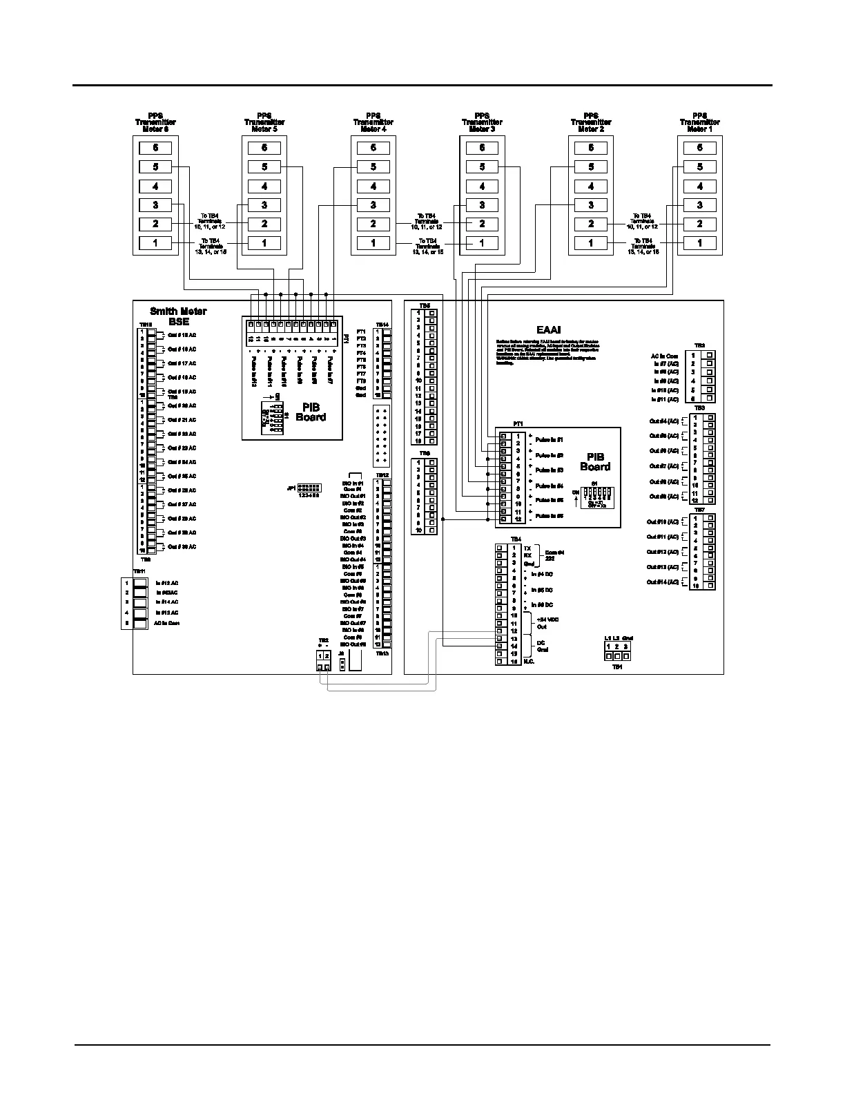
Figure 18. Wiring Diagram, PPS Dual Pulse Transmitter
Note: Wiring between transmitter and Accuload should be done with a shielded cable per each transmitter. If selected cable utilizes
twisted pairs, do not run more than one signal in a twisted pair.
Caution: For clarity, shields not shown. Connect shields to terminals 3, 13, 14, or 15 of Terminal Block 4.
PPST Terminal Connections:
1: Common
2: Input Power
3: Signal B Output
4: B
¯ Output
5: Signal A Output
6: A
¯ Output