Section IV – Diagrams
MN06135 Issue/Rev. 1.3 (6/17) 60
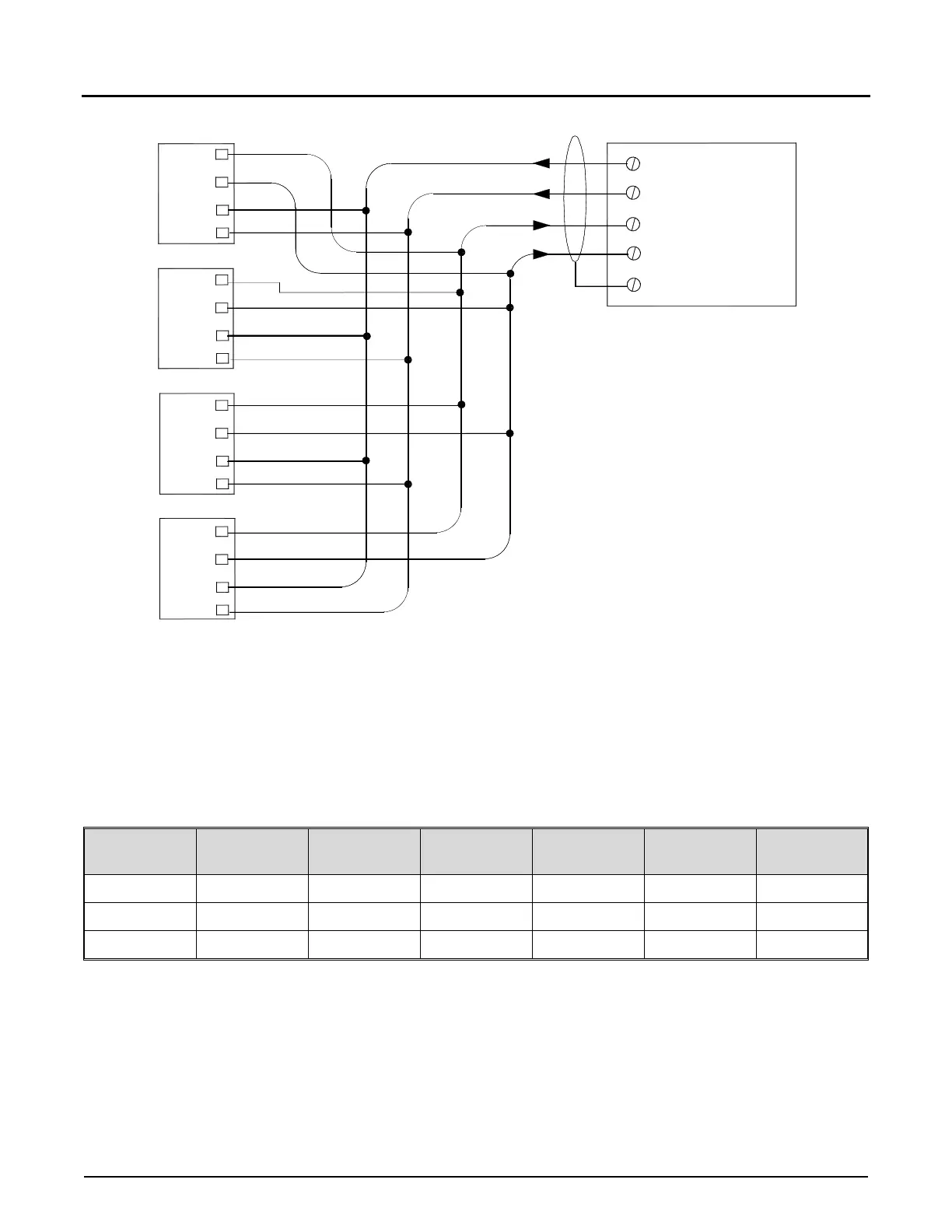
Figure 48. EIA-485 Multi-Drop Communications
The figure shows the typical wiring scheme for multi-drop communications between a communications device and
multiple AccuLoad IIIs. Refer to the table below for pin numbers on each of the EIA-485 communication ports.
Note that the shield is to be terminated at the communication device.
Comm Port Tx + Tx - Rx + Rx - Board
Terminal
Block
1 6 7 8 9 KDC TB1
2 4 5 6 7 KDC TB2
3 1 2 3 4 KDC TB3
Table 14. EIA-485 Communication Ports
Note: Communications Ports 1 and 2 can be either EIA-485 or EIA-232.
AccuLoad III
Tx -
Rx +
Communicating
Device
Tx/485+
Rx/485-
Shield
Tx +
Rx -
Rx -
Rx +
Tx -
Tx +
Tx +
Tx -
Rx +
Rx -
AccuLoad III
AccuLoad III
AccuLoad III
Rx -
Rx +
Tx -
Tx +
Tx/485-
Rx/485+