Section IV – Diagrams
MN06135 Issue/Rev. 1.3 (6/17) 72
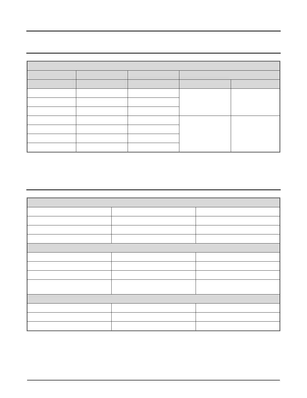
Communications (AICB Boards)
Communications
Type Function Terminal Jumpers
CN4 CN5
EIA - 232 TX TB2 (4) 1-2 Out
3-4 Out
5-6 In
1-2 Out
3-4 Out
EIA – 232 RX TB2 (2)
EIA – 232 Com TB1 (2)
EIA - 485 RX+ TB2 (1) 1-2 Out
3-4 Out
5-6 Out
1-2 In
3-4 In
EIA - 485 RX- TB2 (2)
EIA - 485 TX+ TB2 (3)
EIA - 485 TX- TB2 (4)
Table 18. Communications (AICB Boards)
Jumper Locations
Transmitter Power
Designation Jumpers Description
CN2 1 – 2 24V – +V Out
CN2 3 – 4 12V – +V Out
CN2 5 – 6 5V – +V Out
Communications
Designation Jumper Description
CN4 1 – 2 In Address 200, Out Address 100*
CN4 3 – 4 In 9600 Baud, Out 38.4K Baud
CN4 5 – 6
In 232 Communications,
Out 485 Communications
Last Unit Only (Termination of Communications with AccuLoad)
Designation Jumper Description
CN5 1 – 2 In EIA 485, Out EIA 232
CN5 3 – 4 In EIA 485, Out EIA 232
Table 19. Jumper Locations
*Note: For ALIII-S hardware and Additives 5 through 14 on the ALIII-Q hardware, jumper must be out (Address 100). For Additives 15 through
24, the jumper must be installed (Address 200).
Note: Jumpers CN1 and CN3 for factory use only.