Section IV – Diagrams
MN06135 Issue/Rev. 1.3 (6/17) 9
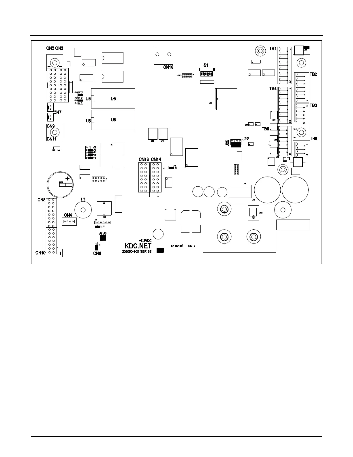
Figure 5. KDC Layout
Configurable jumper locations are heavily circled on the diagram above. It is important to note that all but one of
these jumpers, J22, are factory defaults and should not be configured by the user. The proper settings are provid-
ed below so if one of these is accidentally changed, it can be returned to its original position. J22 is the jumper
used to zero the passcodes and security input access level (151-157). Jumpers are configured using the plugs
that fit over the jumper prongs. A jumper with no prongs plugged, or with one prong plugged, is OUT. A jumper
with both prongs plugged is IN.
Note: Should Program Mode be inaccessible after changing PROMs, or if the operator loses or forgets the access code, set J22 to In, then
power up. Entry to the program mode is provided. Check passcodes and remove jumper J22 when finished.
* Jumper 23 if removed indicates there is not a BSE board in the System (ALIII-S Hardware)
** Jumper 24 if removed indicates there is only one display (ALIII-S Hardware)
*** For units shipped prior to October 2001: J6 must be in the “in" position for Optrex Model DMF5003N.
For units shipped after October 2001: J6 must be in the “out" position for Model MTG-2406 displays.
**** For units shipped prior to August 2005: J5 must be in the “out” position. After August 2005 and for all units with Rev. B displays,
the Jumper J5 must be in the “in” position.