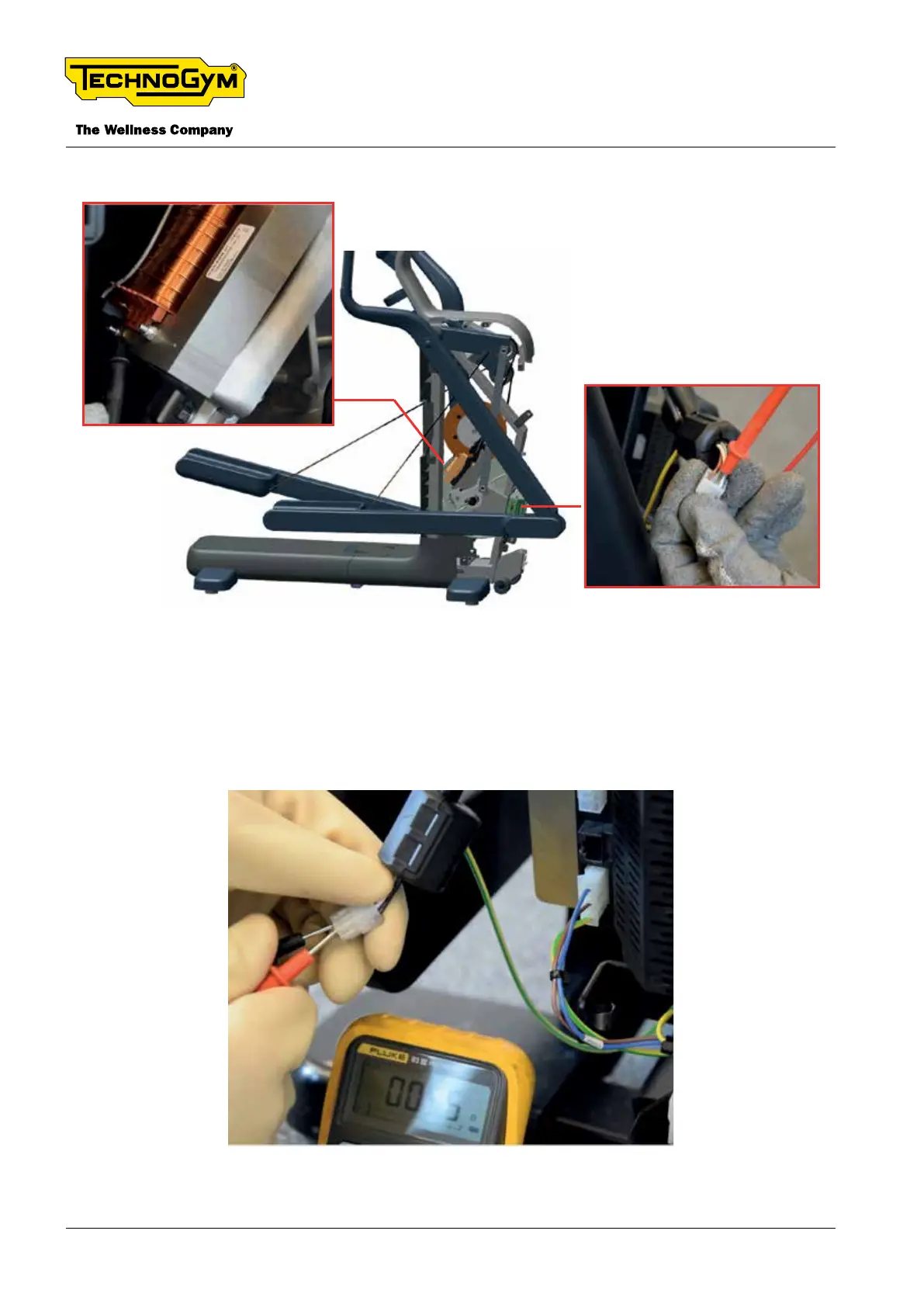
- between PIN 2 and PIN 2 (grey)
Fig. 23
[3]: Check the electromagnetic brake: disconnect the 3x2 pin connector from the brake board. Put
the probes of the tester in PIN 1 (inductive brake + - white) and PIN 2 (inductive brake - - grey).
The measured value must be around 5 Ω, excluding the impedance of the probes of the tester and
the cable.
Fig. 24
TECHNOGYM ELLIPTICAL Technical Service Guide
Rev. 1.1
- 50 -
Uncontrolled copy if printed Uncontrolled copy if printed