PURESTRENGTH & BENCHES: Guida all'Assistenza Tecnica - rev. 4.1
Page 5.48
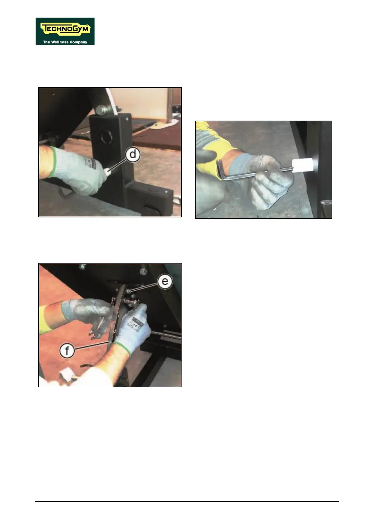
Figure 5.13-17
6. Lift the selector and block it with a pin or a
wrench, as shown in the figure at the side.
7. Fit a paper tube (d) in the
hole to prevent the
screw from falling inside the frame, as shown
below.
Figure 5.13-18
8.
Remove the internal screw using a 8mm
hexagonal key.
Figure 5.13-19
9. Unscrew the 4 screws (e) using 2 opposed
13mm wrenches.
10. Remove the selector (f).
To reassemble the removed parts, carry out the
disassembling steps in reverse order.