PURESTRENGTH & BENCHES: Guida all'Assistenza Tecnica - rev. 4.1
Page 5.2
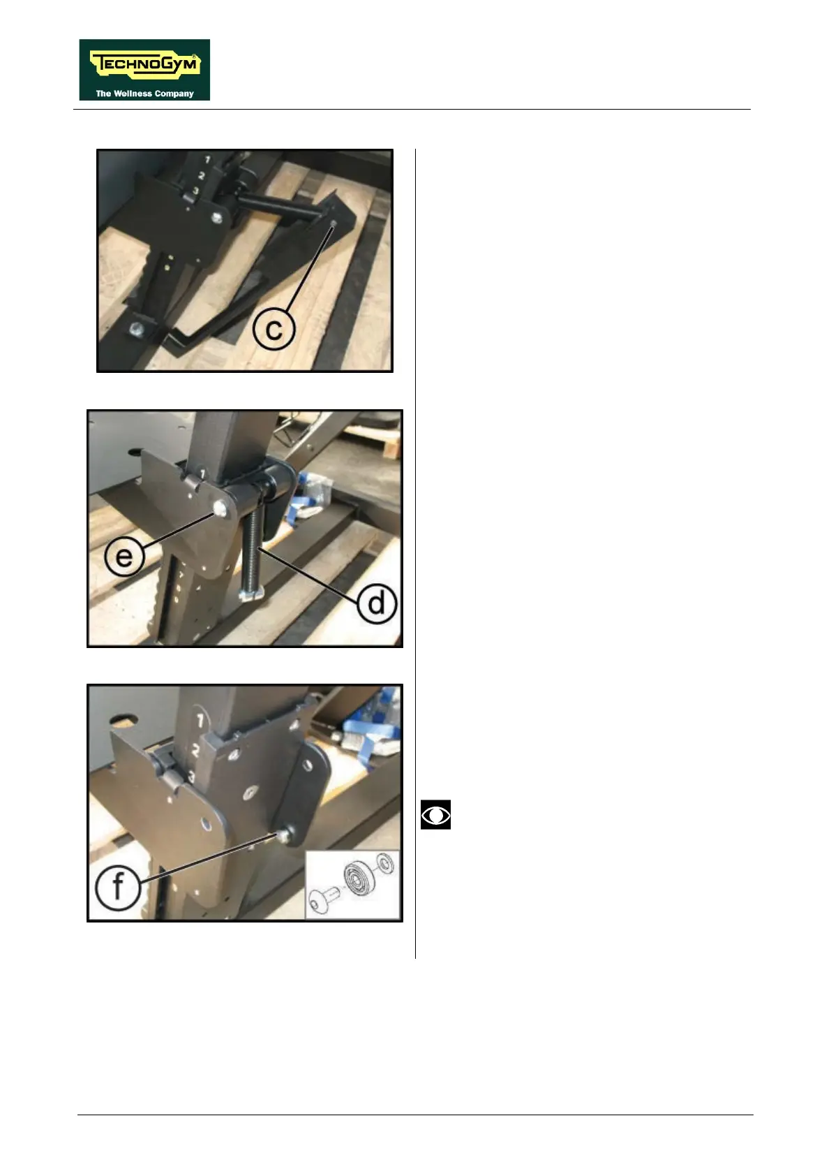
Figure 5.1-3
4. Remove the guard by pulling it up out of its
lower seats.
5. To remove the pin (c)
the side walls of the guard slightly outward.
Figure 5.1-4
6. Remove the spring (d) by unscrewing the 2
screws (e) using a 6mm hexagonal key.
Figure 5.1-5
7. Remove the 2 bearings by unscrewing the
screws (f) with a 4mm hexagonal key.
8.
Remove the seat frame by pulling it out from
the front side of the equipment.
To reassemble the bearings, refer to the
diagram shown in the figure.
Continued on following page
→