Measuring Signals
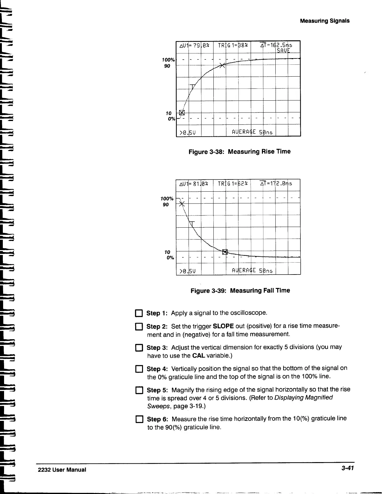
Figure 3-38: Measuring Rise Time
L
c
i?
iz
c
LT
r
r
LI
L'
LI
LI
LI:
LI
LI
r
LI
L'
LL
LZ
LZ1
LI
iz
C:
Lf
c
U
L'
U
L'
U
2232
User Manual
3-47
--
---
-*--a
-
---
-
--
-
-
Figure 3-39: Measuring Fall Time
Step 1
:
Apply a signal to the oscilloscope.
Step
2:
Set the trigger
SLOPE
out (positive) for a rise time measure-
ment and in (negative) for a fall time measurement.
Step 3:
Adjust the vertical dimension for exactly
5
divisions (you may
have to use the
CAL
variable.)
Step
4:
Vertically position the signal so that the bottom of the signal on
the 0% graticule line and the top of the signal is on the 100% line.
Step
5:
Magnify the rising edge of the signal horizontally so that the rise
time is spread over
4
or
5
divisions. (Refer to
Displaying Magnified
Sweeps,
page
3-1
9.)
Step
6:
Measure the rise time horizontally from the lo(%) graticule line
to the
go(%) graticule line.

 Loading...


