Displaying Signals
Step
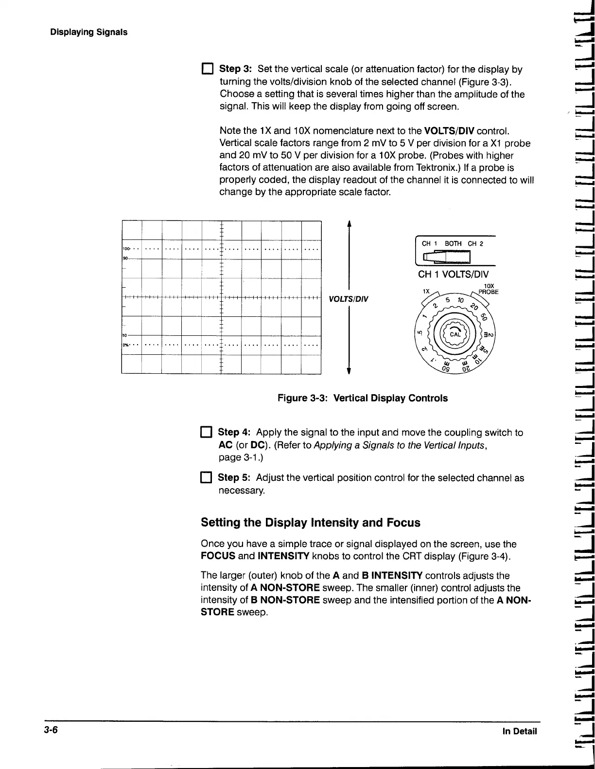
3:
Set the vertical scale (or attenuation factor) for the display by
turning the
volts/division knob of the selected channel (Figure 3-3).
Choose a setting that is several times higher than the amplitude of the
signal. This will keep the display from going off screen.
Note the
1X
and
1 OX
nomenclature next to the VOLTSIDIV control.
Vertical scale factors range from
2
mV to
5
V per division for a
X1
probe
and
20
mV to
50
V per division for a
10X
probe. (Probes with higher
factors of attenuation are also available from Tektronix.) If a probe is
properly coded, the display readout of the channel it is connected to will
change by the appropriate scale factor.
CH
1
VOLTSIDIV
I
VOLTSIDIV
Figure
3-3:
Vertical Display Controls
Step
4:
Apply the signal to the input and move the coupling switch to
AC (or DC). (Refer to Applying a Signals to the Vertical Inputs,
page 3-1
.)
Step
5:
Adjust the vertical position control for the selected channel as
necessary.
Setting the Display Intensity and
Focus
Once you have a simple trace or signal displayed on the screen, use the
FOCUS and INTENSITY knobs to control the CRT display (Figure 3-4).
The larger (outer) knob of the A and
B
INTENSITY controls adjusts the
intensity of A NON-STORE sweep. The smaller (inner) control adjusts the
intensity of
B
NON-STORE sweep and the intensified portion of the A NON-
STORE sweep.
u
3-6
In Detail
3

 Loading...


