Displaying
Signals
Step
4:
Select
Scan
and press the
ACQ
menu button again to exit the
menu.
Step
5:
Press the
SGL SWP
button.
Note that the acquisition scans across the screen from left to right until it
reaches the trigger point and then rolls right to left from the trigger point until
a trigger occurs.
When a trigger occurs, the oscilloscope scans left to right until the record is
filled and then freezes the display.
If you want to retain a waveform for later reference, transfer it to a
SAVE REF
memory location.
To rearm the trigger circuit, press
SGL SWP
again. The previous acquisition
record will now disappear and the oscilloscope will be ready for the next
trigger.
Accumulating Signal Peaks (ACCPEAK)
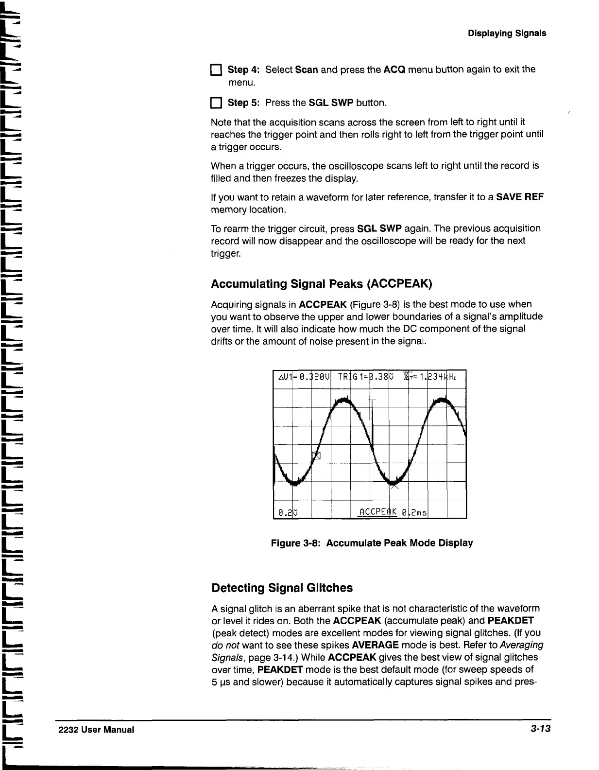
Acquiring signals in
ACCPEAK
(Figure 3-8) is the best mode to use when
you want to observe the upper and lower boundaries of a signal's amplitude
over time. It will also indicate how much the
DC
component of the signal
drifts or the amount of noise present in the signal.
iz
iz
r
r
iz
iE
r
r
r
r
iz
r
iz
iz
iz
-
L
iz
2232
User
Manual
3-13
-
I
-
-
-
-
Figure
3-8:
Accumulate Peak
Mode
Display
Detecting Signal Glitches
A signal glitch is an aberrant spike that is not characteristic of the waveform
or level it rides on. Both the
ACCPEAK
(accumulate peak) and
PEAKDET
(peak detect) modes are excellent modes for viewing signal glitches. (If you
do not want to see these spikes
AVERAGE
mode is best. Refer to Averaging
Signals, page 3-14.) While
ACCPEAK
gives the best view of signal glitches
over time,
PEAKDET
mode is the best default mode (for sweep speeds of
5
ps and slower) because it automatically captures signal spikes and pres-

 Loading...


