Start
Up
Table
1-1
:
Basic Analog Display Setup (Cont.)
Control Section Control Name Control Setting
Horizontal
Controls
POSITION
MODE
A
SECIDIV
SECIDIV Variable
XI
0
Magnifier
Midrange
A
.2
ms
CAL detent
Off (knob in)
A
Trigger
Controls
VAR HOLDOFF
Mode
SLOPE
LEVEL
A
&
B SOURCE
A COUPL
NORM
P-P AUTO
Out (positive)
Midrange
VERT MODE
NORM
Display Mode
Control
STOREINON-STORE NON-STORE (button out)
Adjusting Trace Rotation
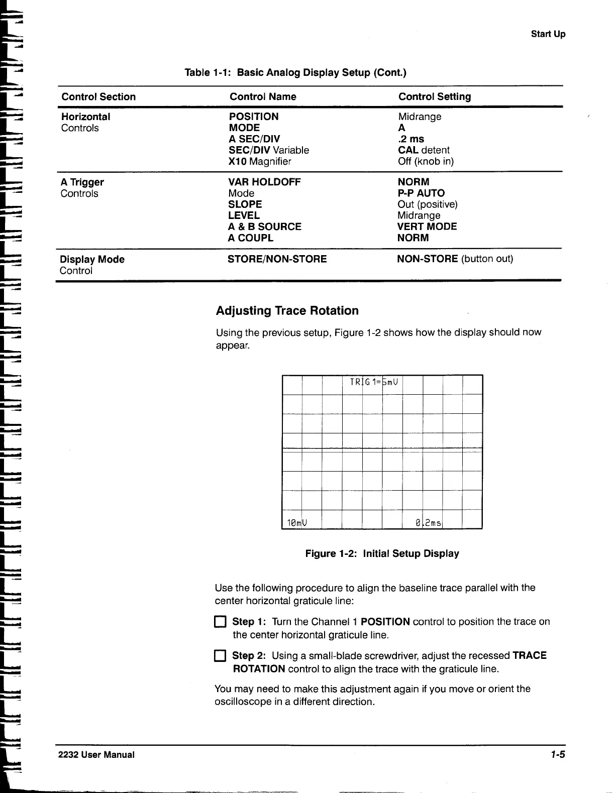
Using the previous setup, Figure
1-2
shows how the display should now
appear.
Figure
1-2:
Initial Setup Display
Use the following procedure to align the baseline trace parallel with the
center horizontal graticule line:
Step
1:
Turn the Channel
1
POSITION control to position the trace on
the center horizontal graticule line.
Step
2:
Using a small-blade screwdriver, adjust the recessed TRACE
ROTATION control to align the trace with the graticule line.
You may need to make this adjustment again if you move or orient the
oscilloscope in a different direction.
2232
User
Manual
1-5

 Loading...


