Measuring Signals
C]
Step
4:
Push the
CURSORS
knob in to select the other cursor and
position it on the upper point.
C]
Step
5:
Note the
A
volts (change or difference in volts) readout in the
upper left corner of the display.
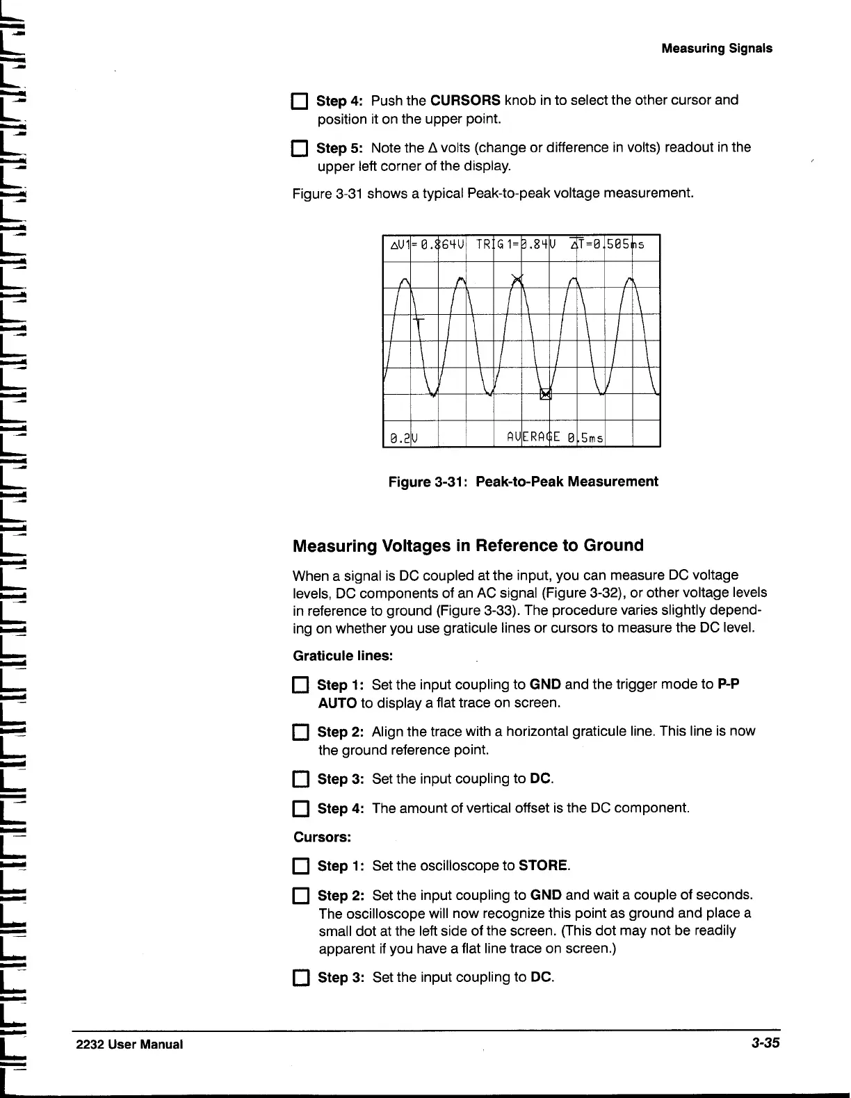
Figure 3-31 shows a typical Peak-to-peak voltage measurement.
Figure 3-31
:
Peak-to-Peak Measurement
Measuring Voltages in Reference to Ground
When a signal is DC coupled at the input, you can measure DC voltage
levels, DC components of an AC signal (Figure 3-32), or other voltage levels
in reference to ground (Figure 3-33). The procedure varies slightly depend-
ing on whether you use graticule lines or cursors to measure the DC level.
Graticule lines:
C]
Step 1:
Set the input coupling to
GND
and the trigger mode to
P-P
AUTO
to display a flat trace on screen.
C]
Step
2:
Align the trace with a horizontal graticule line. This line is now
the ground reference point.
C]
Step
3:
Set the input coupling to
DC.
C]
Step
4:
The amount of vertical offset is the DC component.
Cursors:
C]
Step 1
:
Set the oscilloscope to
STORE.
Step
2:
Set the input coupling to
GND
and wait a couple of seconds.
The oscilloscope will now recognize this point as ground and place a
small dot at the left side of the screen. (This dot may not be readily
apparent if you have a flat line trace on screen.)
C]
Step 3:
Set the input coupling to
DC.
2232
User Manual
3-35

 Loading...


