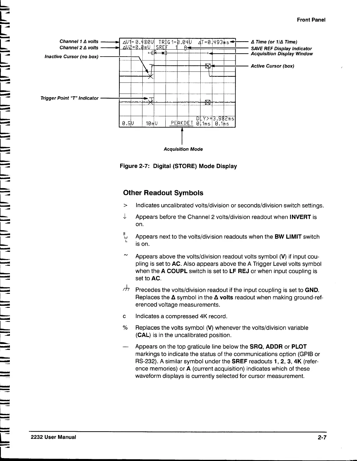
Channel
1
A
volts
Channel
2 A
volts
Inactive Cursor (no box)
Trigger Point
"T"
Indicator
Acquisition Mode
Figure
2-7:
Digital (STORE)
Mode
Display
Front Panel
A
Time (or
llA
Time)
SAVE REF Display lndicator
Acquisition Display Window
Active Cursor (box)
Other Readout Symbols
>
lndicates uncalibrated volts/division or seconds/division switch settings.
Appears before the Channel 2
volts/division readout when INVERT is
on.
B
u
Appears next to the volts/division readouts when the
BW
LIMIT switch
is on.
"
Appears above the volts/division readout volts symbol
(V)
if input cou-
pling is set to AC. Also appears above the A Trigger Level volts symbol
when the A COUPL switch is set to LF REJ or when input coupling is
set to AC.
Precedes the
volts/division readout if the input coupling is set to GND.
Replaces the
A
symbol in the
A
volts readout when making ground-ref-
erenced voltage measurements.
c
lndicates a compressed
4K
record.
%
Replaces the volts symbol (V) whenever the volts/division variable
(CAL) is in the uncalibrated position.
-
Appears on the top graticule line below the SRQ, ADDR or PLOT
markings to indicate the status of the communications option (GPIB or
RS-232). A similar symbol under the SREF readouts
1,
2,
3,
4K
(refer-
ence memories) or A (current acquisition) indicates which of these
waveform displays is currently selected for cursor measurement.
L
e
2232
User
Manual
2-7

 Loading...


