Appendix
C:
Performance Verification
Trigger
A
&
B
SOURCE
Storage
STOREINON-STORE
Procedure Steps:
Step
1
:
Check Internal A and
B
Triggering
NON-STORE
(button out)
a. Connect the leveled sine wave generator output via a 50
fl
cable
and a 50
LI
termination to the CH 1
OR
X
input connector.
b. Set the generator to produce a 10 MHz,
3.5
division display.
c. Set the
CH
1
VOLTSIDIV
switch to 50 mV.
d. CHECK
-
Stable display can be obtained by adjusting the
A
Trigger
LEVEL
control for each switch combination given in Table A-13.
e. Set the Horizontal
MODE
switch to
B.
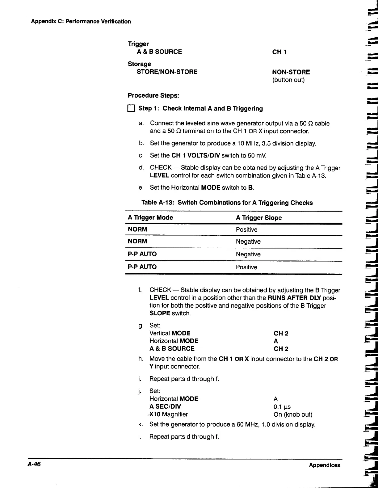
Table A-13: Switch Combinations for A Triggering Checks
A Trigger Mode
A Trigger Slope
NORM
Positive
NORM
Negative
P-P AUTO
Negative
P-P AUTO
Positive
f.
CHECK- Stable display can be obtained by adjusting the
B
Trigger
LEVEL
control in a position other than the
RUNS AFTER DLY
posi-
tion for both the positive and negative positions of the
B
Trigger
SLOPE
switch.
g. Set:
Vertical
MODE CH
2
Horizontal
MODE A
A
&
B
SOURCE
CH
2
h. Move the cable from the
CH
1
OR
X
input connector to the
CH
2
OR
Y
input connector.
i.
Repeat parts
d
through
f.
j. Set:
Horizontal
MODE
A
SECIDIV
XI0
Magnifier
A
0.1 ps
On (knob out)
k. Set the generator to produce a 60 MHz, 1.0 division display.
I.
Repeat parts
d through f.
A-46
Appendices

 Loading...


