Start Up
Step
3:
Check the fuse to be sure it is the proper type and rating. The
2232
is shipped with the UL@ approved fuse installed.
Step
4:
Be sure you have the appropriate operating environment.
Specifications for temperature, relative humidity, altitude, vibrations, and
emissions are included in the Specifications appendix of
this
manual.
C]
Step
5:
Leave space for cooling. Do this by verifying that there are no
airflow obstructions within
2
inches (5.1 cm) of the air-intake on the
sides of the cabinet and exhaust holes on the rear of the cabinet (where
the fan operates).
Step
6:
Connect the power cord from the rear-panel power connector to
the power system.
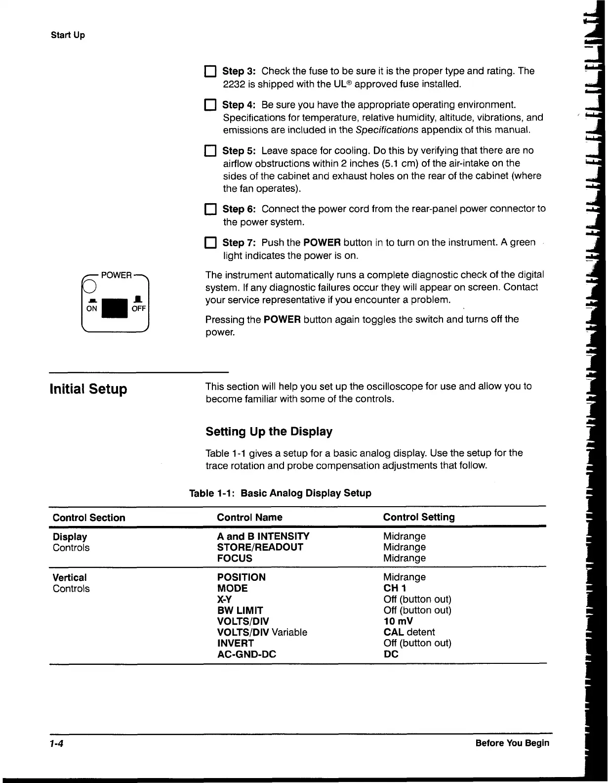
Step
7:
Push the POWER button in to turn on the instrument.
A
green
light indicates the power is on.
The instrument automatically runs a complete diagnostic check of the digital
system. If any diagnostic failures occur they will appear on screen. Contact
your service representative if you encounter
a
problem.
Pressing the POWER button again toggles the switch and turns off the
power.
Initial
Setup
This section will help you set up the oscilloscope for use and allow you to
become familiar with some of the controls.
Setting
Up
the
Display
Table 1-1 gives a setup for a basic analog display. Use the setup for the
trace rotation and probe compensation adjustments that follow.
Table
1-1
:
Basic Analog Display Setup
Control Section Control Name Control Setting
Display A and B INTENSITY Midrange
Controls
STORE/READOUT Midrange
FOCUS Midrange
Vertical POSITION Midrange
Controls MODE
CH
1
X-Y
Off (button out)
BW
LIMIT
Off (button out)
VOLTSIDIV
10
mV
VOLTSIDIV Variable
CAL detent
INVERT
Off (button out)
AC-GND-DC DC
7
-4
Before You Begin

 Loading...


