Appendix
C:
Performance Verification
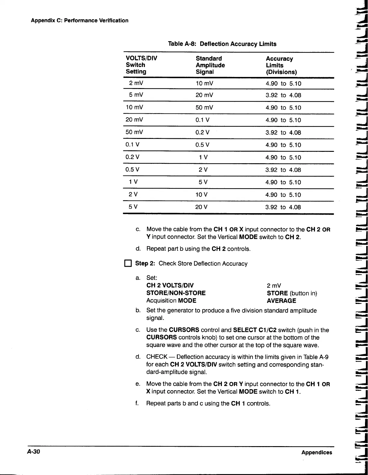
Table A-8: Deflection Accuracy Limits
VOLTSIDIV
Switch
Setting
Standard
Amplitude
Signal
Accuracy
Limits
(Divisions)
c. Move the cable from the
CH 1 OR
X
input connector to the
CH 2 OR
Y
input connector. Set the Vertical
MODE
switch to
CH 2.
d. Repeat part b using the
CH 2
controls.
Step 2:
Check Store Deflection Accuracy
a. Set:
CH 2 VOLTSIDIV
STOREINON-STORE
Acquisition
MODE
2
mV
STORE
(button in)
AVERAGE
b. Set the generator to produce a five division standard amplitude
signal.
c. Use the
CURSORS
control and
SELECT C1lC2
switch (push in the
CURSORS
controls knob) to set one cursor at the bottom of the
square wave and the other cursor at the top of the square wave.
d. CHECK
-
Deflection accuracy is within the limits given in Table A-9
for each
CH 2 VOLTSIDIV
switch setting and corresponding stan-
dard-amplitude signal.
e. Move the cable from the
CH 2 OR
Y
input connector to the
CH
1
OR
X
input connector. Set the Vertical
MODE
switch to
CH 1.
f.
Repeat parts b and c using the
CH 1
controls.
Appendices

 Loading...


