Displaying Signals
Triggering on Signals
Triggering is an important function of the oscilloscope that allows you to
stabilize the display of a signal. The trigger circuit of the oscilloscope syn-
chronizes the beginning of a sweep (or acquisition) with a particular point on
the rising or falling edge of a trigger signal. Without a proper trigger, the
signal display may either "free-run" or not appear at all.
Triggering on Repetitive Signals
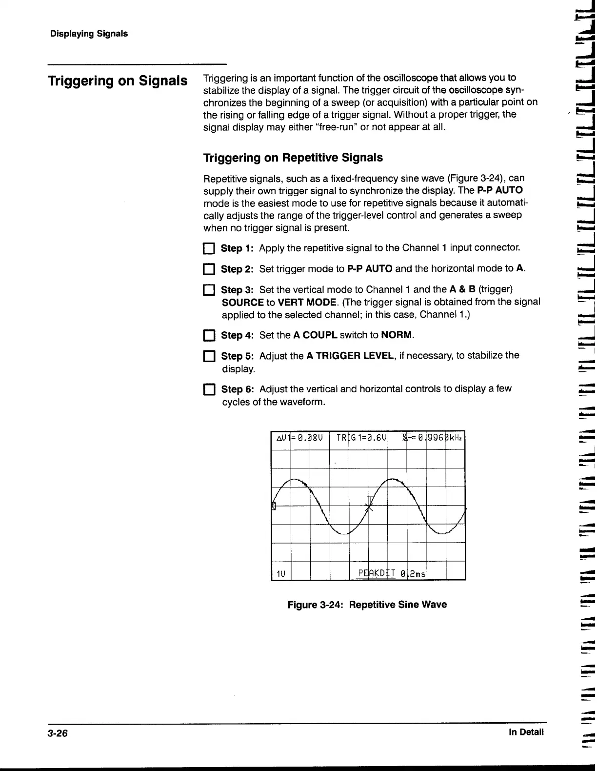
Repetitive signals, such as a fixed-frequency sine wave (Figure
3-24),
can
supply their own trigger signal to synchronize the display. The
P-P AUTO
mode is the easiest mode to use for repetitive signals because it automati-
cally adjusts the range of the trigger-level control and generates a sweep
when no trigger signal is present.
Step
1
:
Apply the repetitive signal to the Channel
1
input connector.
Step
2:
Set trigger mode to
P-P AUTO
and the horizontal mode to
A.
Step
3:
Set the vertical mode to Channel
1
and the
A
&
B
(trigger)
SOURCE
to
VERT MODE.
(The trigger signal is obtained from the signal
applied to the selected channel; in this case, Channel
1
.)
Step 4:
Set the
A
COUPL
switch to
NORM.
Step
5:
Adjust the
A TRIGGER LEVEL,
if necessary, to stabilize the
display.
Step
6:
Adjust the vertical and horizontal controls to display a few
cycles of the waveform.
Figure 3-24: Repetitive Sine Wave
4
-
-
3-26
In Detail
d
-
-

 Loading...


