TELOS TWOX12 USER’S MANUAL
INSTALLATION
CHAPTER 2 28
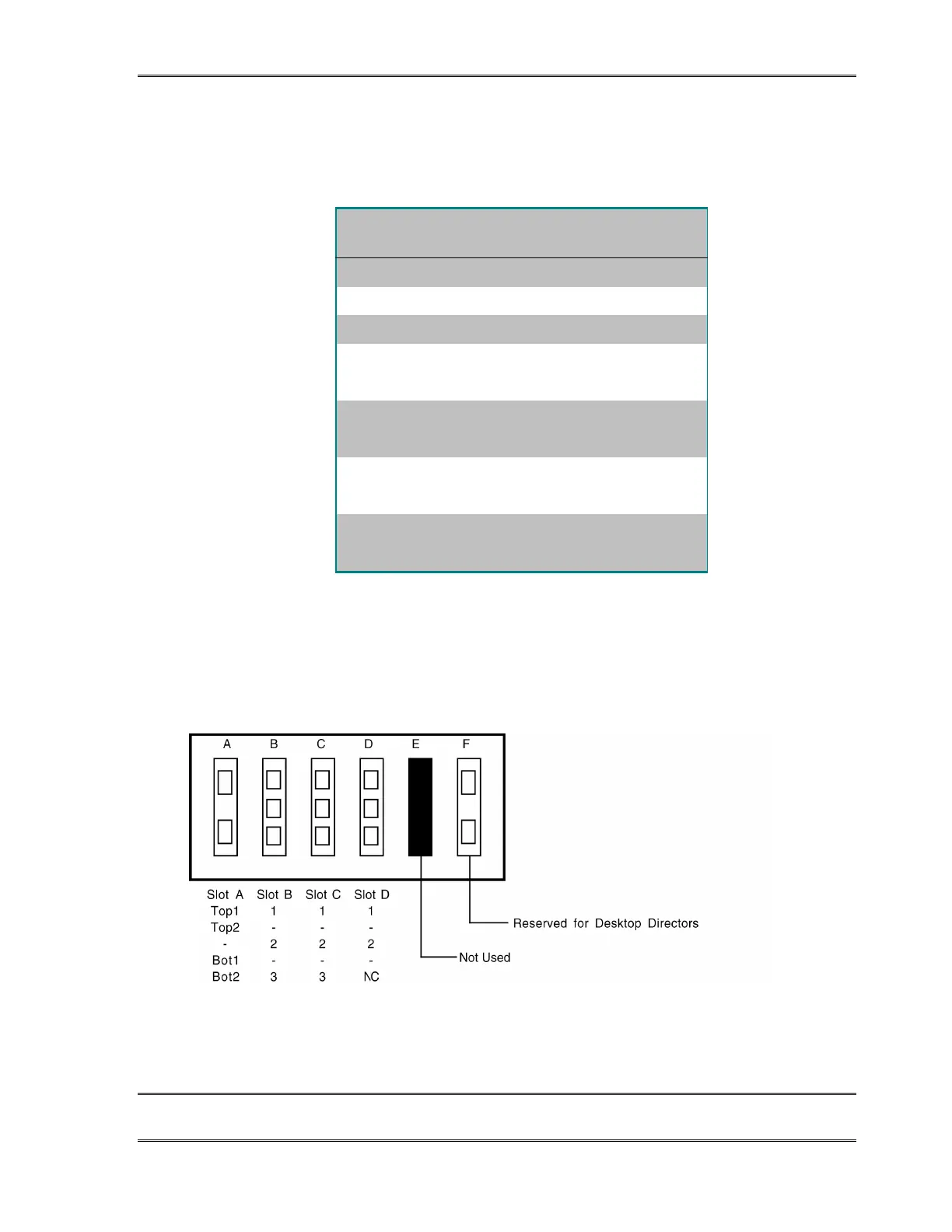
The correspondence between the interface slot to the system “Line” number for the above
mixed TWOx12 configuration is illustrated in the following table:
Slot
Designation
Channel ID #
(Telephone #)
System
“Line” #
A1 1 1
A2 2 2
A3 3 3
B Top1
B Top2
4 (DN/MSN 1)
4 (DN/MSN 2)
4
5
B Bot1
B Bot2
5 (DN/MSN 1)
5 (DN/MSN 2)
6
7
C Top1
C Top2
6 (DN/MSN 1)
6 (DN/MSN 2)
8
9
C Bot1
C Bot2
7 (DN/MSN 1)
7 (DN/MSN 2)
10
11
This table shows the relationship between the TWOx12's connectors, the Telco circuits, and the
system "line" numbers for the mixed ISDN/POTS TWOx12 described above. See section 3 for a
form you can use to organize this Information prior to programming your system.
B) 1 ISDN interface (slot A) and 3 Analog interfaces (slots B, C, & D) for a total of 12
lines (note that the bottom jack of the analog card in slot D will be inactive in this
configuration)
A mixed interface TWOx12 with an ISDN interface card in slot A and POTS interface cards in slots
B, C, & D. The ISDN interface supports two ISDN BRI circuits while POTS interface supports 3
circuits. Since each BRI has two telco channels (or “Lines”) there are 4 channels per BRI interface
card. Since the TWOx12 is a 12 line system, the last POTS port (D3) is not used in this
configuration.