TELOS TWOX12 USER’S MANUAL
INSTALLATION
CHAPTER 2 48
• All inputs are specially treated to accept either a voltage (up to 24 VDC), or a closure
to ground, which may be provided by switches, relays, or logic outputs. The inputs are
active low.
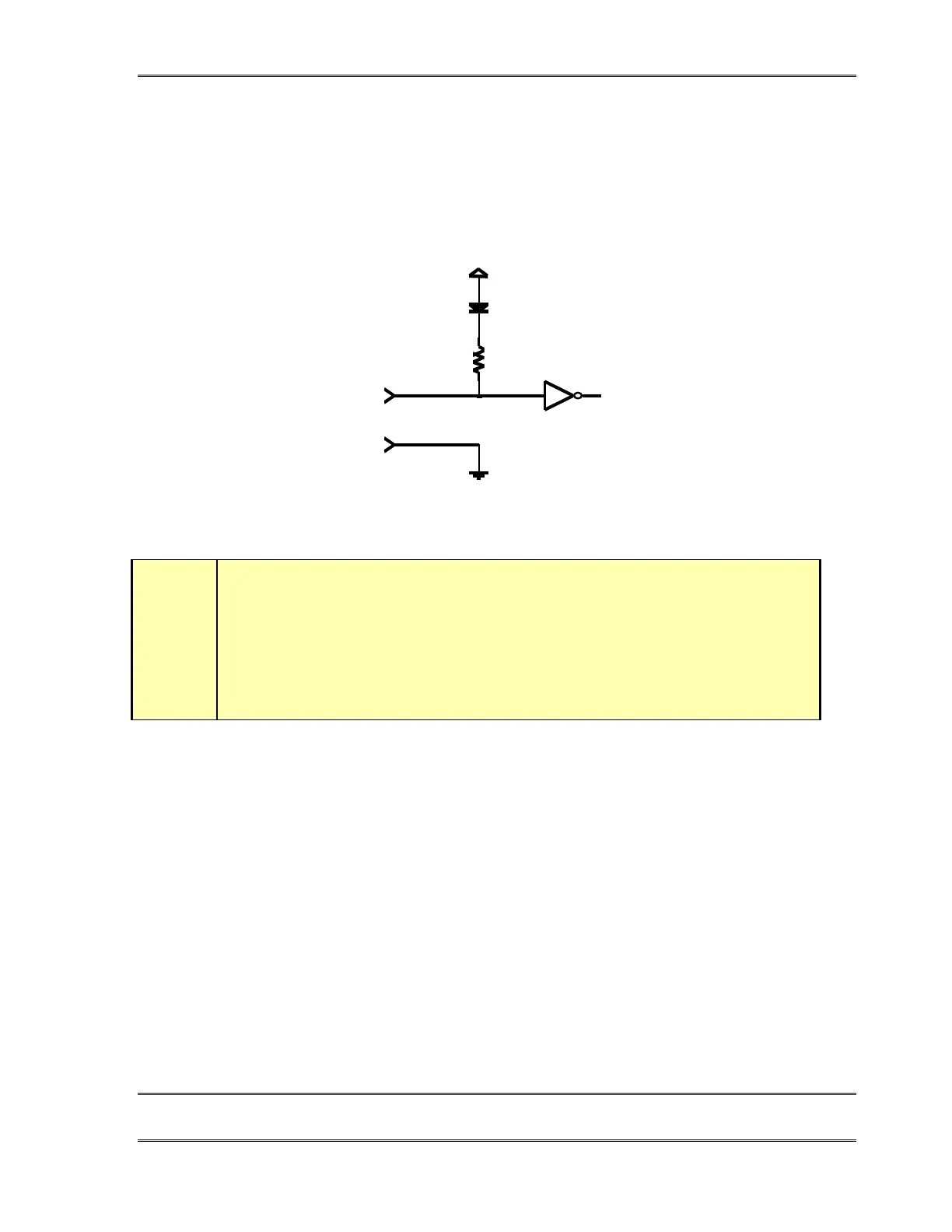
• A built in 1kΩ pull up resistor is provided so TTL outputs can be directly interfaced.
See below for a simplified schematic of the input circuitry.
30v max
+5V
Parallel logic input circuit
t
DEEP TECH NOTE!
The TWO’s “universal” logic input circuit can be used with switch or relay closures,
voltage levels up to 24 Vdc, or logic outputs – either “totem- pole” or open- collector.
Outputs
Outputs are open collector to ground and can sink up to 400 mA of current. Their functions
are shown on the previous page.
These will require a pull-up resistor to function with other logic inputs. Some equipment
has the pull-ups built into their control inputs – check the device’s manual to be sure. If
there is no pull-up in the interfaced equipment, you’ll have to add one. An appropriate
value is 2.2KΩ.
Current should be limited to 400ma maximum per output with total output restricted to 1
amp (200ma each output if all five will be used).
If used with a relay or LED, then tie your external power source ground to pin 1 (or use the
5 VDC power supplied on pin 8 and run this power source through your device, with a
resistor in series to limit maximum current to 400ma.
For additional information refer to section 7.3.3.