SERVICE 5-40 Manual 0-4691
5
D. Pressure Switch/Solenoid Assembly Replacement
The Pressure Switch and Solenoid Valve are one Assembly. Disconnect primary input power and bleed down the system.
1. Remove the power supply cover per Section 5.09-A.
2. Disconnect the following wires:
a. Wires #10 and #11 from the Pressure Switch Assembly.
b. Wires #8 and #9 from the Solenoid Assembly.
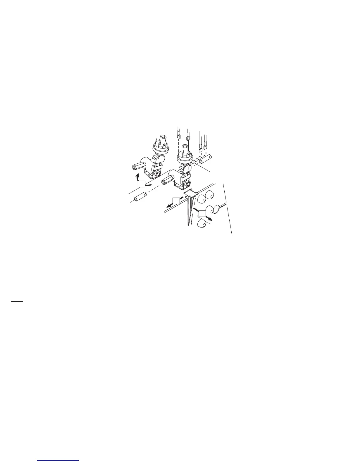
3. Push the clip on the front of the Heatsink Shroud to the left to release the Solenoid Assembly. Dislodge the Assembly
from underneath the clip on the top of the Heatsink Shroud.
Heatsink
Shroud
Dislodge Solenoid
Assembly
Push Clip
to the left to
release Solenoid
Assembly
Art # A-03705
2
3
1
4. Release the hose from the Adapter Fitting on the input side of the Solenoid Assembly. Hold a wrench or similar tool
against the locking ring on the Fitting, then pull on the hose to release it.
5. Release the hose from the Adapter Fitting on the output side of the Solenoid Assembly.
6. Install the replacement Pressure Switch/Solenoid Assembly by reversing steps 2-5. Once installed, the Solenoid Assem-
bly should fit securely on the Heatsink Shroud. It should not be moveable.
7. Re-install the power supply cover.