Manual 0-4691 3-13 INSTALLATION
3
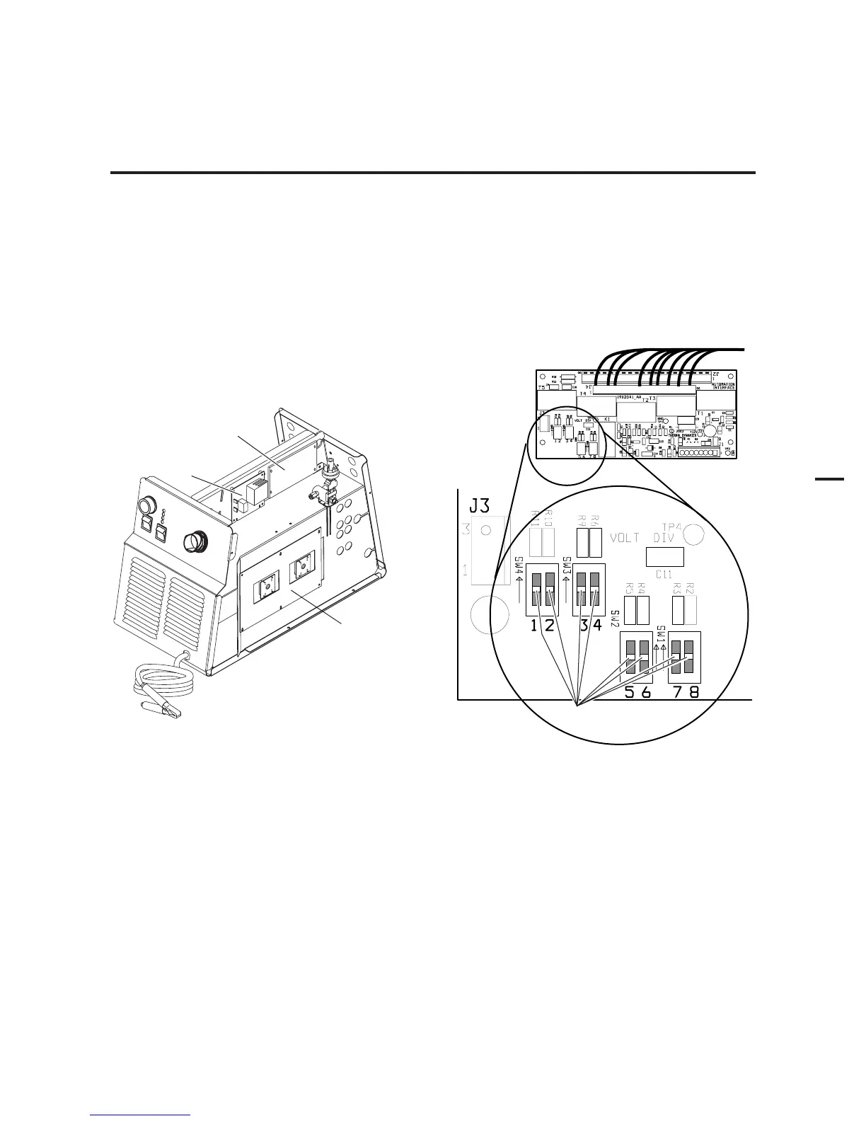
3.10 Automation Interface PC Board Set-up
The Automation Interface PC board includes switches that must be set to adapt the Interface Board to the automation system
being used.
NOTE
The switches are factory-set for the Thermal Dynamics SC-11 Standoff Control.
For operation with any other CNC equipment, refer to the CNC system documents to determine the division factor the CNC
system requires. Proceed as follows:
1. Set the interface control board switches as indicated in the appropriate chart in the Appendix pages. The division factors
are listed in the right-hand column of each chart.
Automation
Interface
PC Board
Art # A-03902
Pilot PC
Board
Output Power
PC Board
Automation Interface PC Board
Art # A-03757
Switches
8 7 6 5 4 3 2 1
2. Re-install the Power Supply cover.