EasyManuals Logo

Thermal Dynamics CUTMASTER 151 User Manual

Thermal Dynamics CUTMASTER 151
172 pages
To Next Page IconTo Next Page
To Previous Page IconTo Previous Page
Page #153 background imageLoading...
Page #153 background image
Manual 0-4691 A-23 APPENDIX
A
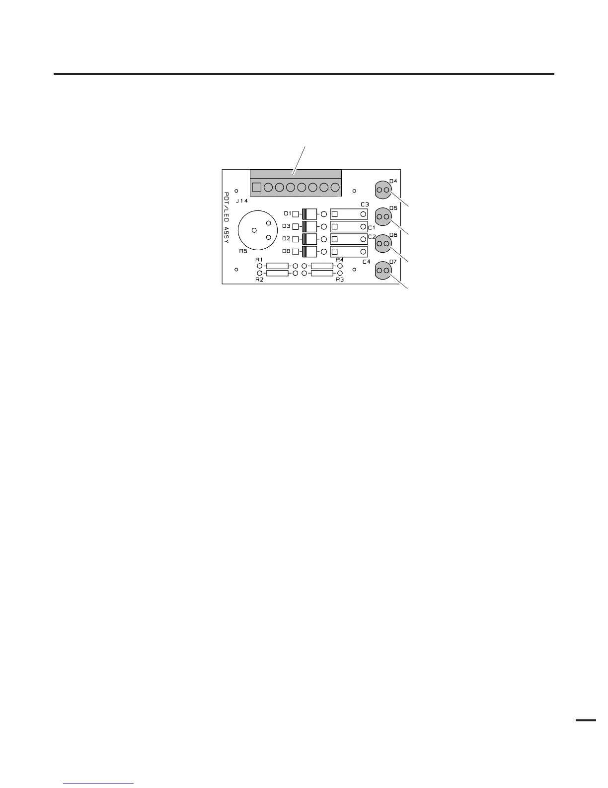
APPENDIX 22: POT / LED BOARD LAYOUT
J14
D4
D5
D7
D6
A-03712
Pot/LED PC Board Signals
J14-1 from Main PC Board (J27-1) Pot High
J14-2 Main PC Board (J27-2) Pot Wiper
J14-3 from Main PC Board (J27-3) Pot Low
J14-4 12vdc (J27-4)
J14-5 Logic Low Signal for AC OK Indicator from Logic PC Board (J27-5)
J14-6 Logic Low Signal for GAS Indicator from Logic PC Board (J27-6)
J14-7 Logic Low Signal for TEMP Indicator from Logic PC Board (J27-7)
J14-8 Logic Low Signal for DC Indicator from Logic PC Board (J27-8)
D4 Front Panel AC Indicator
D5 Front Panel TEMP Indicator
D6 Front Panel GAS Indicator
D7 Front Panel DC Indicator

Table of Contents

Other manuals for Thermal Dynamics CUTMASTER 151

Questions and Answers:

Question and Answer IconNeed help?

Do you have a question about the Thermal Dynamics CUTMASTER 151 and is the answer not in the manual?

Thermal Dynamics CUTMASTER 151 Specifications

General IconGeneral
BrandThermal Dynamics
ModelCUTMASTER 151
CategoryWelding System
LanguageEnglish

Related product manuals