INSTALLATION 3-14 Manual 0-4691
3
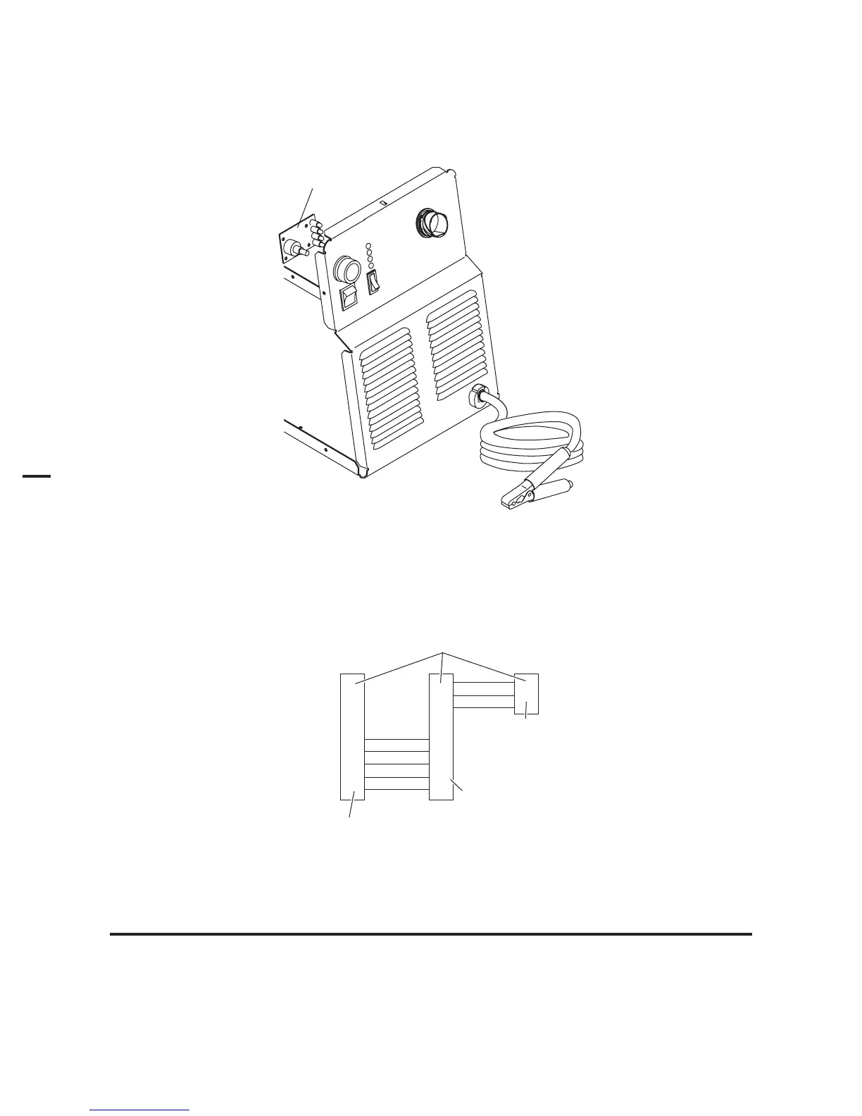
3.11 Optional Remote Current Control Harness Installation
1. Locate the power supply Pot/LED Board just inside the power supply front panel.
Art # A-03964
Pot / LED Board
2. Disconnect and remove the wire harness between the Pot/LED Board and receptacle J22 on the Main PC Board. Keep the
harness for possible future use.
3. The kit includes a wire harness with 3 connectors. Install the harness as follows:
To Pot/LED Board
Receptacle J14
To Automation
Interface Board
Receptacle J3
To Main PC Board
Receptacle J27
Connector Plugs
Art # A-03945
4. Ensure that the wire harness will not interfere with the fit of the power supply cover against the top edge of the
power supply center chassis. Use wire ties as needed to secure the wire harness.
NOTE
Installation of this harness disables the output current control (A) on the front panel of the power supply. Use the
CNC controller to control the output current of the power supply.
5. Re-install the Power Supply cover.