APPENDIX A-18 Manual 0-4691
A
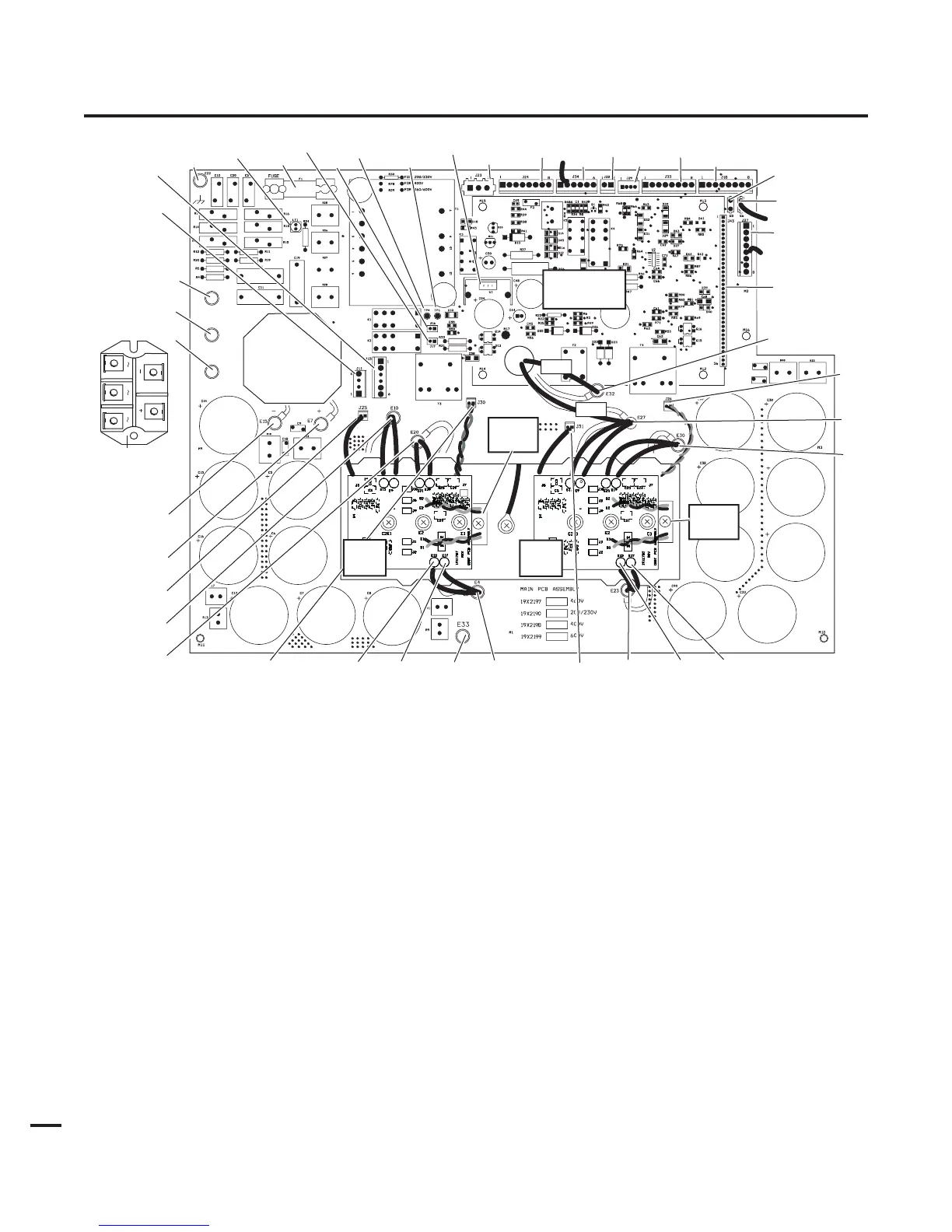
APPENDIX 18: MAIN PC BOARD LAYOUT
6
Main Power PC Board Signals
J11-1 L1 Input
J11-4 L3 Input
J15-1 Fan (M1)
J15-2 Fan (M1)
J15-3 Not used
J15-4 Not used
J15-5 Fan (M2)
J15-6 Fan (M2)
J16-1 Not used
J16-2 Not used
J17-1 Not used
J17-2 Not used
J18-1 Not used
J18-2 Not used
J18-3 28 VAC B
J18-4 28 VAC A
J18-5 On-Off Switch
J18-6 On-Off Switch
J18-7 Run-Set Switch
J18-8 Run-Set Switch
J23-1 Not used
J23-2 Not used
J23-3 Not used
J24-1 Gas Solenoid (SOL1)
J24-2 Gas Solenoid (SOL1)
J24-3 Pressure Switch (PS1)
J24-4 Pressure Switch (PS1)
J24-5 Main Contactor (W1)
J24-6 Main Contactor (W1)
J24-7 Not used
J24-8 Not used
E2
E3
E1
Secondary
Transformer
#32
#27
Input Diode
(mounts to
center chassis)
E1
E3
E2
Fuse
LT1
E33
J25
E10
E20
E7
E15
E30
E27
E32
J26
E23
J23
J24
J34
J33
J32
J18
J29
J27
J43
E5
E6
E4
E12
E17
J30
J31
E22
Art # A-04640
IGBT
PCB
E12
E17
TP4
TP1
J15
J11
J17
J16
U1
IGBT
PCB
IGBT
Module
IGBT
Module
Logic Board
Not Shown