INSTALLATION 3-4 Manual 0-4691
3
3.04 Gas Connections
A. Connecting Gas Supply to Unit
Use only compressed air with this power supply.
An in-line pneumatic dryer & evaporator type air filter, capable of filtering to at least 5 microns, is required when using air from a
compressor. This type filter will insure that moisture, oil, dirt, chips, rust particles, and other contaminants from the supply hose
do not enter the torch. For highly automated applications, a refrigerated drier may be used.
The connection is the same for compressed air from a compressor from high pressure cylinders. Refer to subsection 3.4-B or 3.4-
C if an additional air line filter is to be installed.
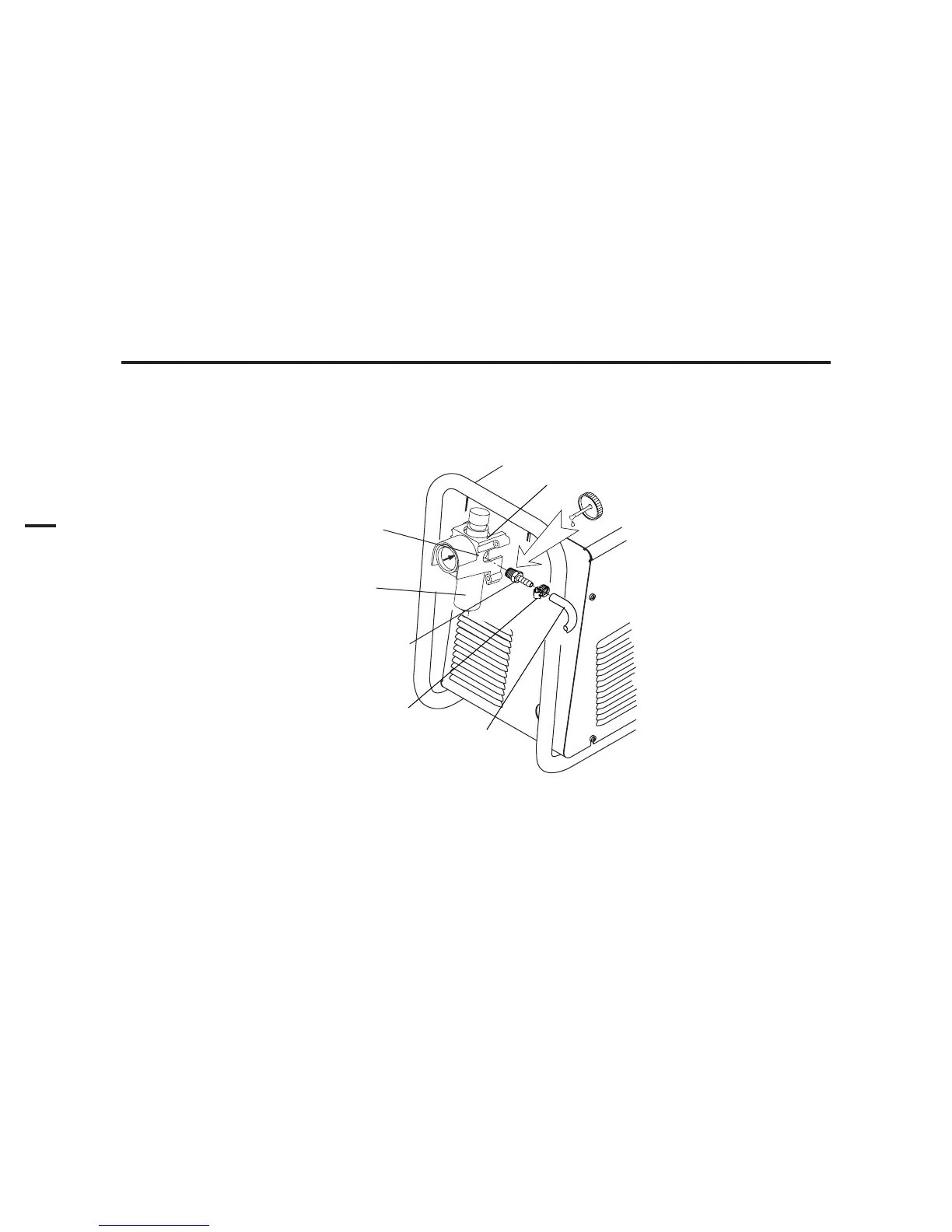
1. Connect the air line to the inlet port. The illustration shows typical fittings as an example. Other fittings can be
used.
NOTE
For a secure seal, apply thread sealant to the fitting threads, according to manufacturer's instructions. Do not use
Teflon tape as a thread sealer, as small particles of the tape may break off and block the small air passages in the torch.
Art # A-02999
Hose Clamp
1/4 NPT to 1/4"
(6mm) Fitting
Regulator/Filter
Assembly
Inlet Port
Gas Supply
Hose
Bowl
Air Connection to Inlet Port