APPENDIX A-20 Manual 0-4691
A
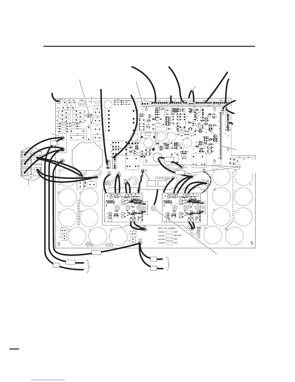
APPENDIX 19: MAIN PC BOARD WIRING LAYOUT
(208/230-Volt POWER SUPPLIES)
Input
Diode
(mounts
to center
chassis)
E2
E3
E1
Art # A-04606
To Input
Contactor
T
o Chassis Ground
To Logic Board
via Connector
To Po w
er Output Board
To Torch
Connector
To On/Off and
Run/Rapid Restart
Set Switches
To Fans
To Main
Input Contactor
Test Connector
To Heat Sink
Temp Sensor
Heat Sink
T
emp Sensor
To Inductor Temp Sensor
T
o Press Switch/Solenoid/Contactor
Fuse
Secondary
Transfor
mer
Copper
Strap
#1
To Input
Contactor
To Auto Interface
Board J1-5
To Auto Interface
Board J1-6
To Main
Transformer
#33
#78
#1
LT1
#32
#27
#2
#3
To POT/LED PCB
(or to
Optional Remote
Current Control )*
* If installed in conjuction with
Automation Interface PC Board
J30
J31