SERVICE 5-28 Manual 0-4691
5
C. RUN / RAPID AUTO RESTART / SET Switch (SW2) Replacement
1. Remove the power supply cover per Section 5.09-A.
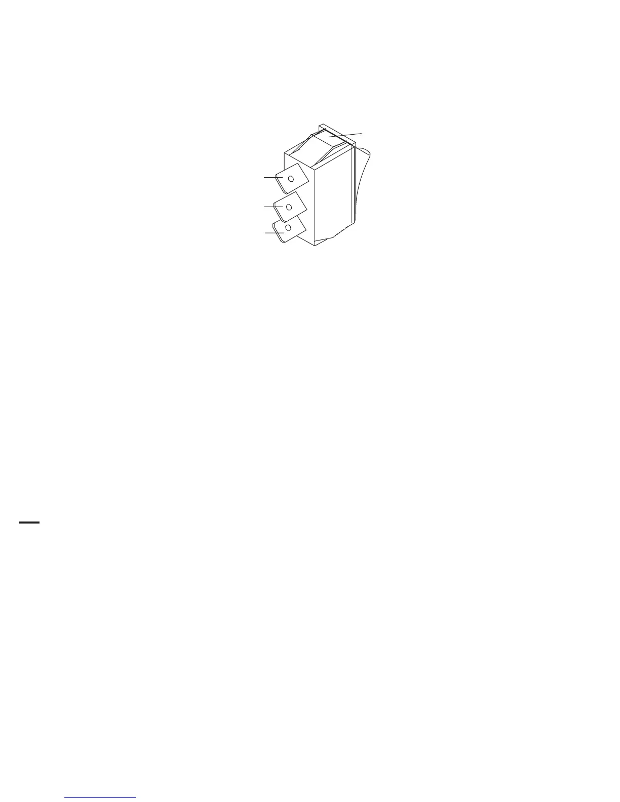
2. Disconnect the wires on the rear of the Switch. Note the location of each wire, as shown:
Art # A-03906
Wire #25
Wire #26
Top clip
Wire #46
3. Squeeze together the clips on the top and bottom of the Switch, then remove the switch through the Front Panel.
4. Install the replacement Switch by reversing the above steps.
5. Reinstall the power supply cover.
D. POT/LED PC Board Replacement
1. Remove the power supply cover per Section 5.09-A.
2. Remove Current Knob .
3. Disconnect wire harness Connector from POT/LED PC Board.
4. Remove PC Board from standoffs.
5. Install the replacement POT/LED PC Board by reversing the above steps.
6. Reinstall the power supply cover.