SERVICE 5-30 Manual 0-4691
5
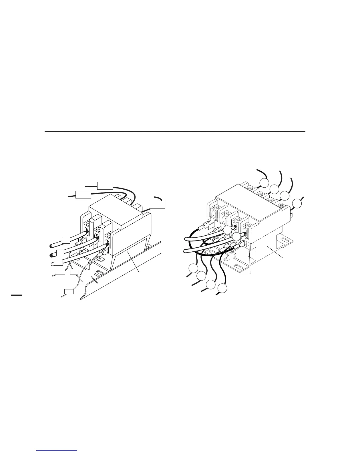
B. Main Input Contactor (W1) Replacement
1. Remove the power supply cover per Section 5.09-A.
2. Label all wires connected to the Input Contactor.
3. Disconnect wires to the Input Contactor from the input cable.
4. Disconnect all other wires connected to the Input Contactor.
5. Remove the two nuts and washers securing the Input Contactor to the base of the power supply.
6. Position the replacement Input Contactor with the row of connectors labeled L toward the rear of the Power Supply.
Fasten in place with the hardware removed previously.
7. Complete the wiring connections as shown.
NOTE
It is important that wires are installed correctly, as shown, to prevent damage to the unit.
8. Reinstall the power supply cover.
Art # A-03194
Main Contactor
#13
#5
L1 L2 L3
T1 T2 T3
To E3
Connections to
Main PCB
#4
#12
To E1
To E2
Input Side
L1
L3
L2
Art # A-03212
L1 L2 L3 L4
T1 T2 T3 T4
#13
#12
#78
L1
L2
Input
Side
#5
#4
#3
#2
#1
Main Contactor
400-Volt, 460-Volt, and 600-Volt Input Contactor 208 / 230-Volt Input Contactor
(3-phase input power connections shown)