Servicing
Pump Replacement
7-18 Model 48i Instruction Manual Thermo Electron Corporation
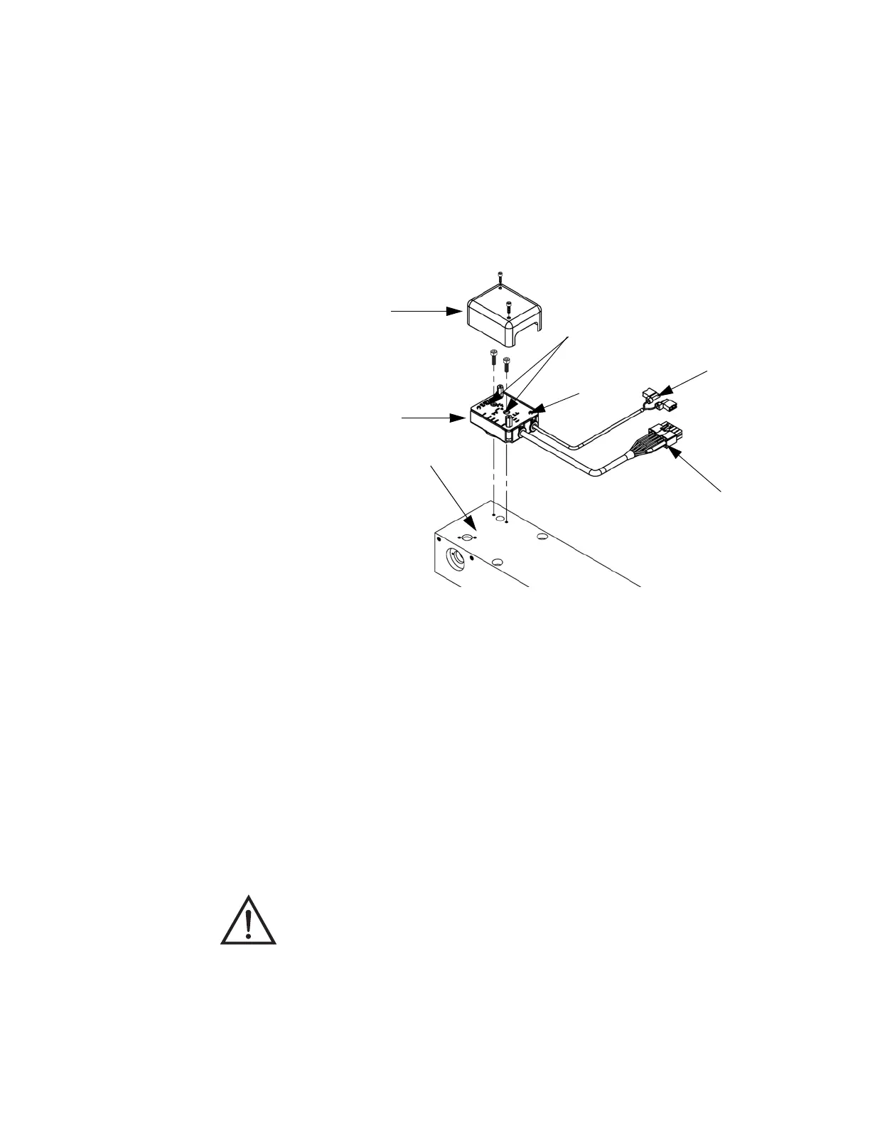
4. Insert an Allen wrench through the access holes in the preamplifier
printed circuit board, and remove the screws holding the detector
assembly to the optical bench. Carefully remove the detector assembly
from the optical bench.
5. Install the new detector assembly by following the previous steps in
reverse.
Figure 7-9. Replacing the Detector/Preamplifier Assembly
Pump Replacement Use the following procedure to rebuild the pump (Figure 7-10).
Equipment Required:
Pump
Nut driver
Philips screwdriver
1. Turn instrument OFF, unplug the power cord, and remove the cover.
To PREAMP on Measurement
Interface Board
To Motor Plate
Preamp Cover
Preamp Board
Access Holes
Optical Bench
Detector Assy
Equipment Damage Some internal components can be damaged by small
amounts of static electricity. A properly grounded antistatic wrist strap must
be worn while handling any internal component.