Redstone™ Optical Spectrum Analyzer Chapter 5: Using the Free-Space Input
Rev C, January 21, 2022 Page 14
The Redstone OSA305 free-space input accepts a beam height of 117 mm (4.6’’) above the table surface. If
the beam height of your experimental setup is not consistent with the free-space input, we recommend using a
periscope assembly, such as Thorlabs’ RS99(/M) periscope, to adjust the beam height to that of the OSA’s
input. Do not use longer posts to elevate the OSA.
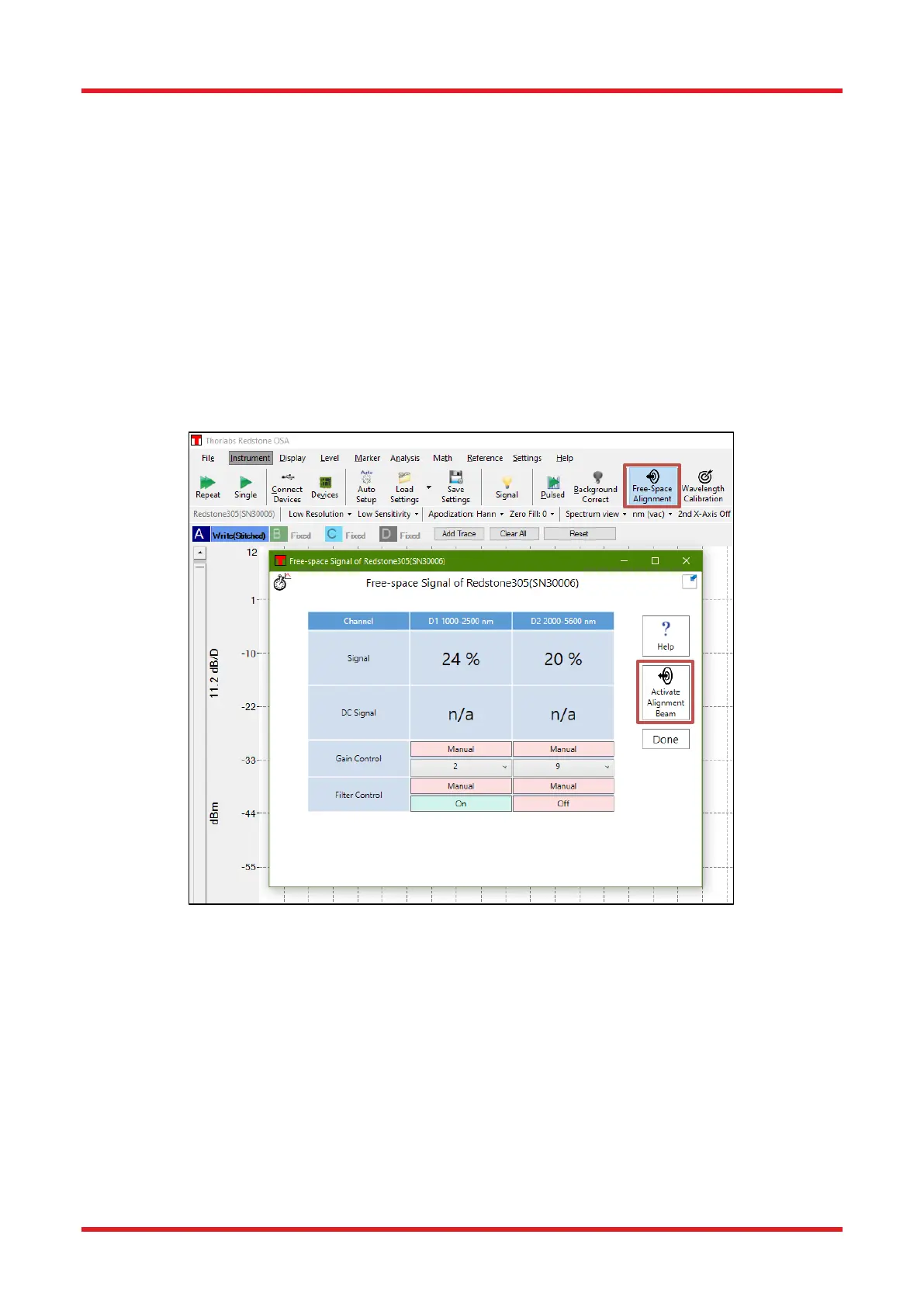
5.2. Activation of Alignment beam
The Redstone OSA305 includes a red alignment laser, which is activated with a button in the “Free-space
Alignment” window (see Figure 9). When the alignment beam is activated, one optical arm of the interferometer
is blocked and no interferometric measurements can be performed, and a warning message will appear in the
OSA software. However, the second optical arm is not blocked and light from this arm is incident on the
detectors. This “DC signal” of the detectors is available when the alignment beam is activated and can be of
assistance in the alignment process.
Note that when the “Free-space Alignment” window is open, the detector offset is disabled and the saturation
level is decreased. When clicking the “Done” button to close the window, the autogain algorithm will try to find
gain and offset settings that optimize the interferogram signal.
Figure 9. Alignment Beam Activation for the Redstone OSA305
The alignment beam should be collinear to the unknown input for optimal measurement accuracy.
To begin the alignment procedure, turn on the alignment beam and proceed with the alignment, following the
instructions in Section 5.3.1. Clicking the “Help” button in the “Free-space Alignment” window in Figure 9 will
open a PDF file with a tutorial with further details and examples.
5.3. Free-Space Beam Alignment Example
5.3.1. Initial Visual Alignment
Figure 10 below shows an example alignment setup, the most important part of which is to include two mirrors
in kinematic mounts. When two mirrors rather than one can be tipped and tilted, the conditions on the position
of the light source are much less stringent. Use the mirror closest to the test source to steer the input source
into the OSA, using a viewing card (such as Thorlabs Item # VRC2) and/or an alignment plate (such as Thorlabs

 Loading...


