Introduction
3DExcavatorIndicateSystems
5
X‐63/X‐63i/X‐62/X‐33/X‐32InstallationandCalibrationManual P/N:7010‐0697
X-63
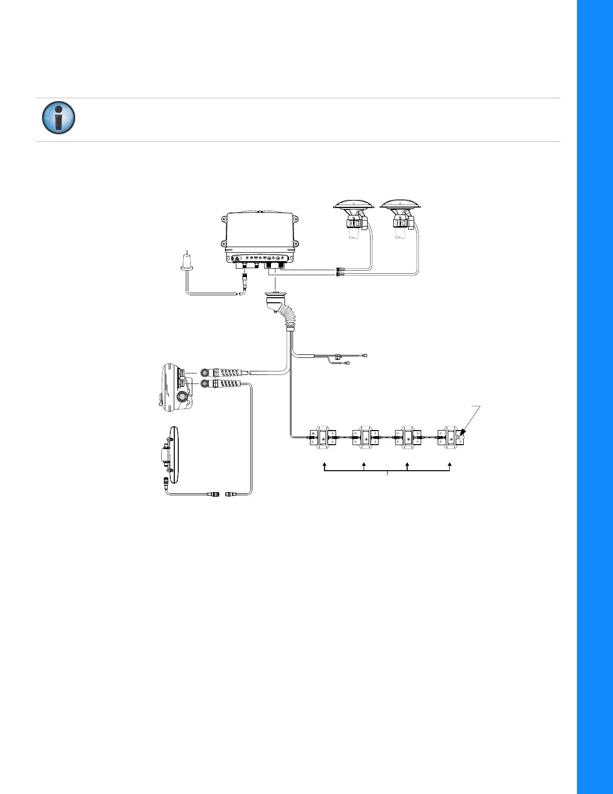
Figure6showsthebasiccablingconnectionsfortheX‐63system.
Wheninstallingcomponents,usethe
Topconsuppliedfuseorfusedpowerfromthemachineofthesamerating.
Figure6:BasicCableConnectionsfortheX‐63System
Systemgroundmustbeconnectedtotheframesideofthegrounddisconnectswitch,not
directlytotheneg ativebatteryterminal.
Attach To
Upper Connector
Aux GPS
Antenna
Main GPS
Antenna
Body Boom Stick Bucket
40-pin
Connector “A”
-
+
Voltage Supply
(Switched Or
Unswitched Is
Acceptable)
Ground To Chassis
7.5 Amp
In-line Fuse
Required
MC-R3 Controller
GX-60
Display
Sensor
Terminator
Radio
Antenna
Optional
Lightbar
TS-1 Tilt Sensors
Optional
Lightbar