8
-EN
Central Control Device (Touch Screen Controller) Installation Manual
3 Installation
• Do not wire communication lines or input/output wiring next to power supply wiring, etc., or house them in the same metal
pipe. Doing so may result in failure.
• Install the main unit away from noise sources.
3-1. Installation of Main Unit Box and Panel
The main unit box can be mounted either from the front or from the rear.
3-1-1. When Installing from the Front
* Since the left and right mounting screws are attached close to each other, please drill the left and right dimensions as
accurately as possible.
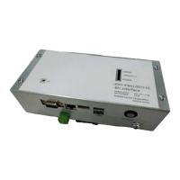
1 Connect the central control wiring, AC adapter, and LAN cable to the main unit.
2 Fit the main unit on to the wall and switch board.
3 Insert a flat head screwdriver, etc. into the groove on the left and right of the bottom of the panel.
There will be a snapping sound and the panel will come off.
• Just insert the screwdriver and do not twist it.
• To prevent the panel from falling, support it during removal.
4 Fix the 4 main unit screws.
5 Close the panel by hooking the panel rear to the top of the main unit.
There will be a snapping sound and the panel will be fixed.
6 When installation is completed, peel off the transparent film.
Main unit box
Fix the panel with the
hooks.
Panel
183
120
100
133
20
93
53
202
190.45.8 5.8
20
20
System controller to wall, etc. fixing hole
dimensions
Do not twist
Hole dimensions to drill in wall
4-Ø4.5 round hole
4-M3 nut

 Loading...