EN
9
-EN
Central Control Device (Touch Screen Controller) Installation Manual
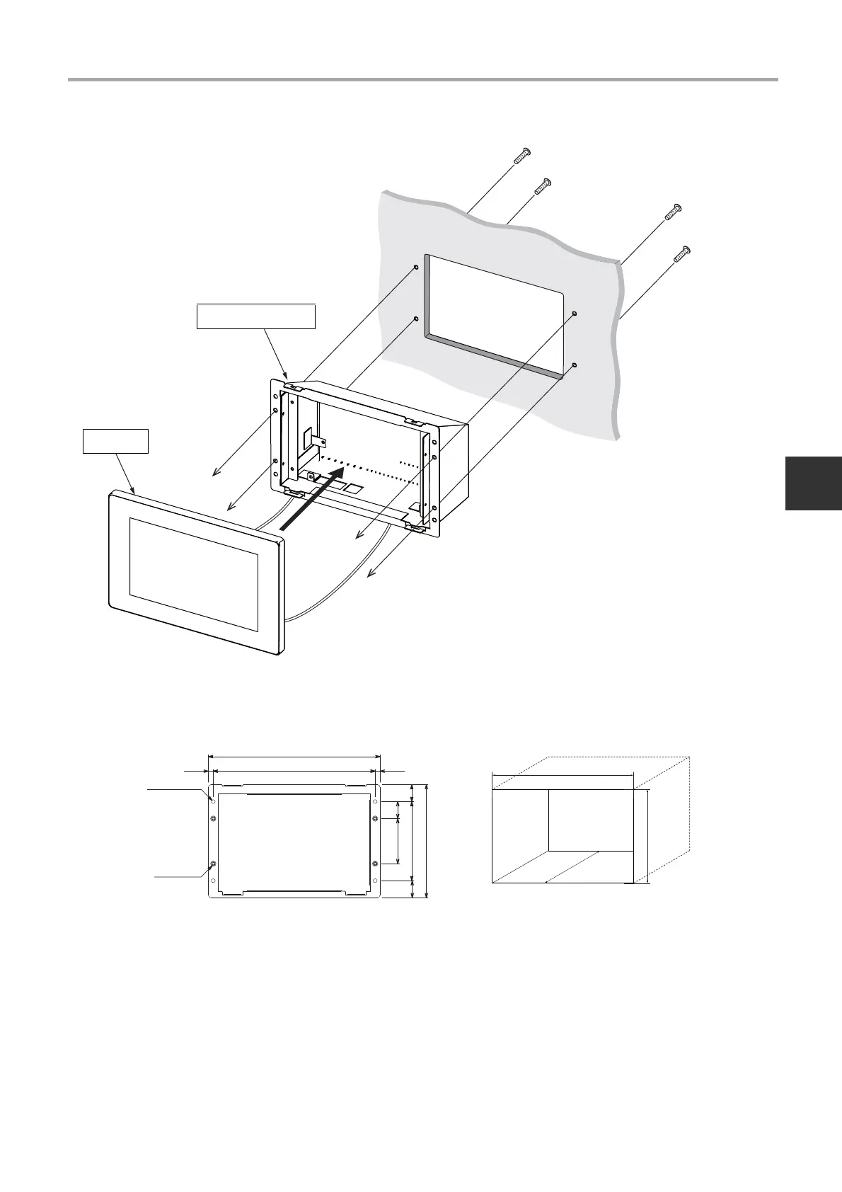
3-1-2. When Installing from the Rear
* Although the panel and the main unit box are separated to explain the screw attachment part in an easy to understand
manner, it is not necessary to remove the main unit box from the panel in actual installation work.
1 Drill four Ø4 holes in the switchboard, wall, etc.
2 Fit the main unit on the switch board, wall, etc.
3 Fix from the rear of the main unit. Please use the supplied M3 × 8 screws.
4 Connect the central control wiring, AC adapter, and LAN cable to the main unit.
5 When installation is completed, peel off the transparent film.
183
120
100
133
20
93
53
202
190.45.8 5.8
20
20
System controller to wall, etc. fixing hole
dimensions
Hole dimensions to drill in wall
4-Ø4.5 round hole
4-M3 nut

 Loading...