EasyManuals Logo

TSC TTP-245 Service Manual

TSC TTP-245
109 pages
To Next Page IconTo Next Page
To Previous Page IconTo Previous Page
Page #25 background imageLoading...
Page #25 background image
TTP-245 / TTP-343
21
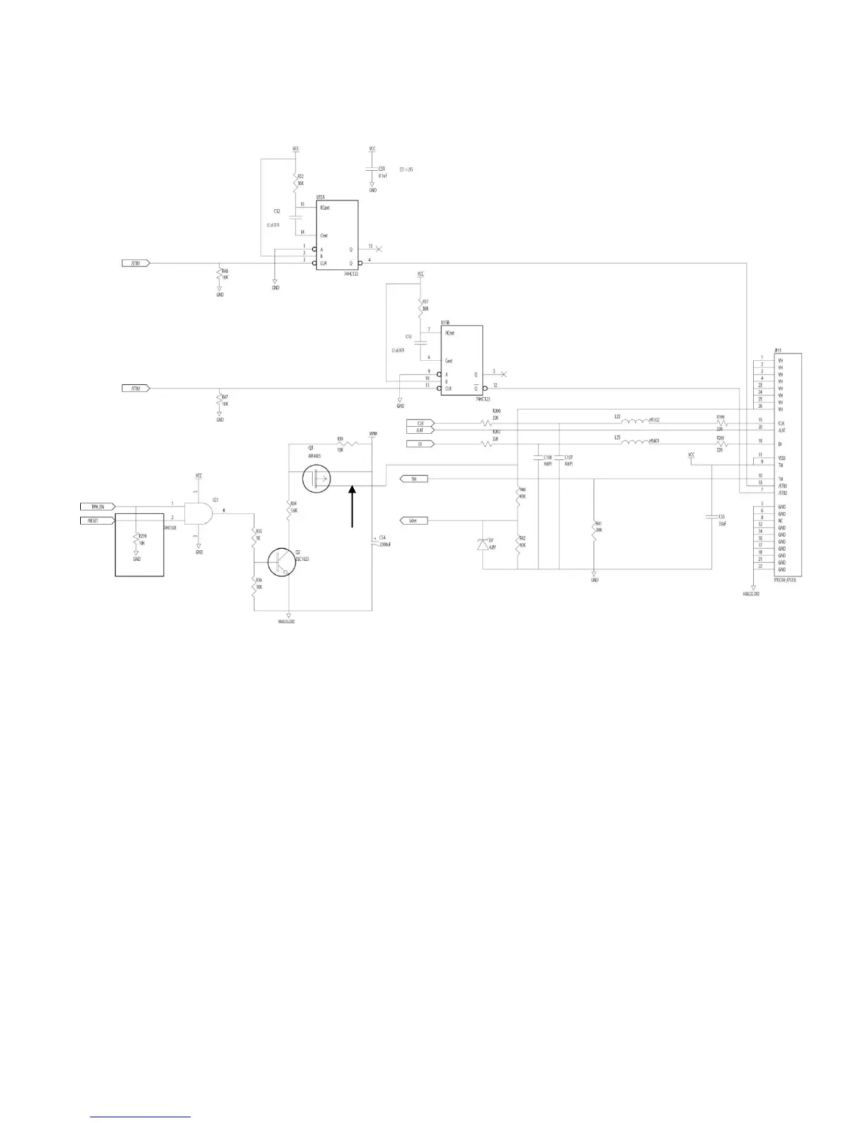
2.7. Print Head Circuit
Fig. 2.7 Print Head Circuit Diagram
CLK and LAT connect to thermal head control clock and data latch respectively.
TPH_EN signal controls the DC24V voltage of the thermal head. When TPH_EN is
high, the thermal head will be separated from 24V (V
DD
). U21 controls protecting print
head. It is used to make sure the power of print head is off when switch off the printer.
Q1 and Q2 are used to limit current of print head.
Both /STB1 and /STB2 determine whether to heat the thermal head or not. The RC
charging time of U15 and 74HC123 limit the heating time of print head to avoid burning
the print head.
DI signal sends printer data to the print head.
TM signal is the temperature/voltage sensor for thermal head.
The Vdet feeds back the voltage and compensates the heat time for voltage accuracy
when printing.
VDD

Table of Contents

Other manuals for TSC TTP-245

Questions and Answers:

Question and Answer IconNeed help?

Do you have a question about the TSC TTP-245 and is the answer not in the manual?

TSC TTP-245 Specifications

General IconGeneral
Print MethodThermal Transfer / Direct Thermal
Resolution203 dpi
Processor32-bit RISC CPU
Max Print Width108 mm (4.25")
Max Print Speed5 inches per second
InterfaceParallel
Ribbon Capacity300 meters
Label Width1 to 4.4 inches
Dimensions232 mm (W) x 156 mm (H) x 288 mm (D)
Power SupplyExternal Universal Switching Power Supply
Operating Temperature5°C to 40°C
Storage Temperature-40°C to 60°C
Operating Humidity25% to 85% non-condensing
Print Length39.37 inches (1000 mm)
Label Thickness0.08 to 0.2 mm

Related product manuals