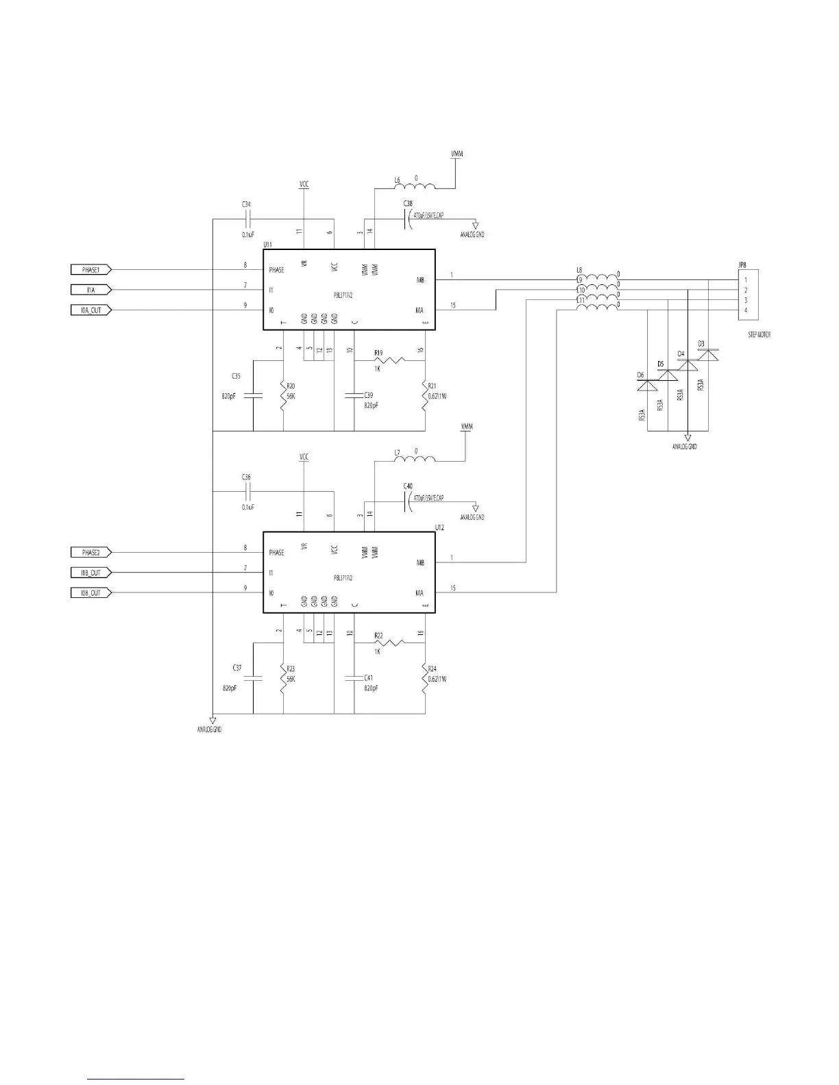
2.8. Stepping Motor Drive / Protection Circuit
Fig. 2.8 Stepping Motor Drive/ Protection Circuit Diagram
Connector, JP8, sends the pattern as shown in table1. The status of I0 & I1
determines the stepping motor power level. The power level pattern is shown in
table2. The motor port is a protection pin. When it is at low level, the power of the
motor system will be closed. Power will be on again until motor pin is the pulse of
high level. Phase1 and phase2 determine the pattern of stepping motor drive
circuit. For example, the sequence of phase 1/ phase 2 in full step mode is 0/0 →
0/1 → 1/1 → 1/0.
 Loading...