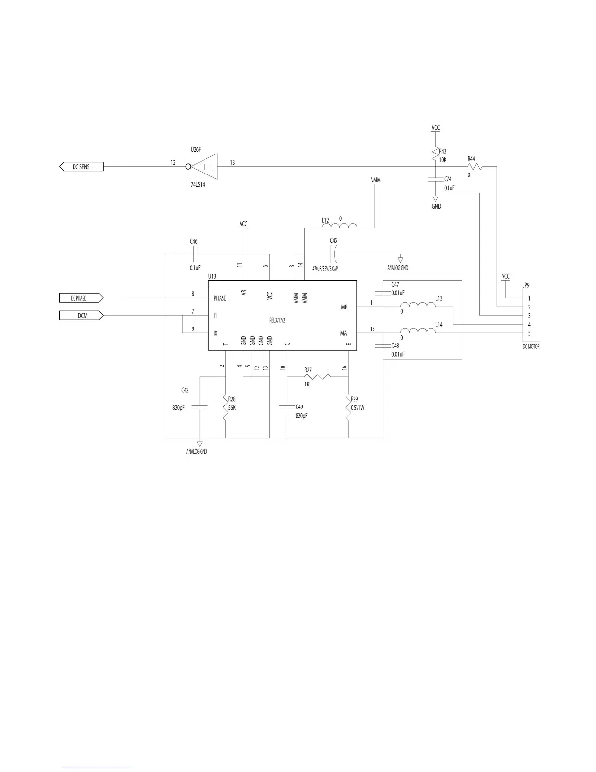
2.15. DC Motor Driver / Encoder Circuit
Fig. 2.15 DC Motor Drive/ Encoder Circuit Diagram
DCM signal is used to switch on/off the motor driver, The DC PHASE signal is to
control the direction of the rotate the encoder circuit, which is used to detect the rotary
rate. DC SENS signal voltage is high when the hole of the gear is detected; otherwise,
it is low.