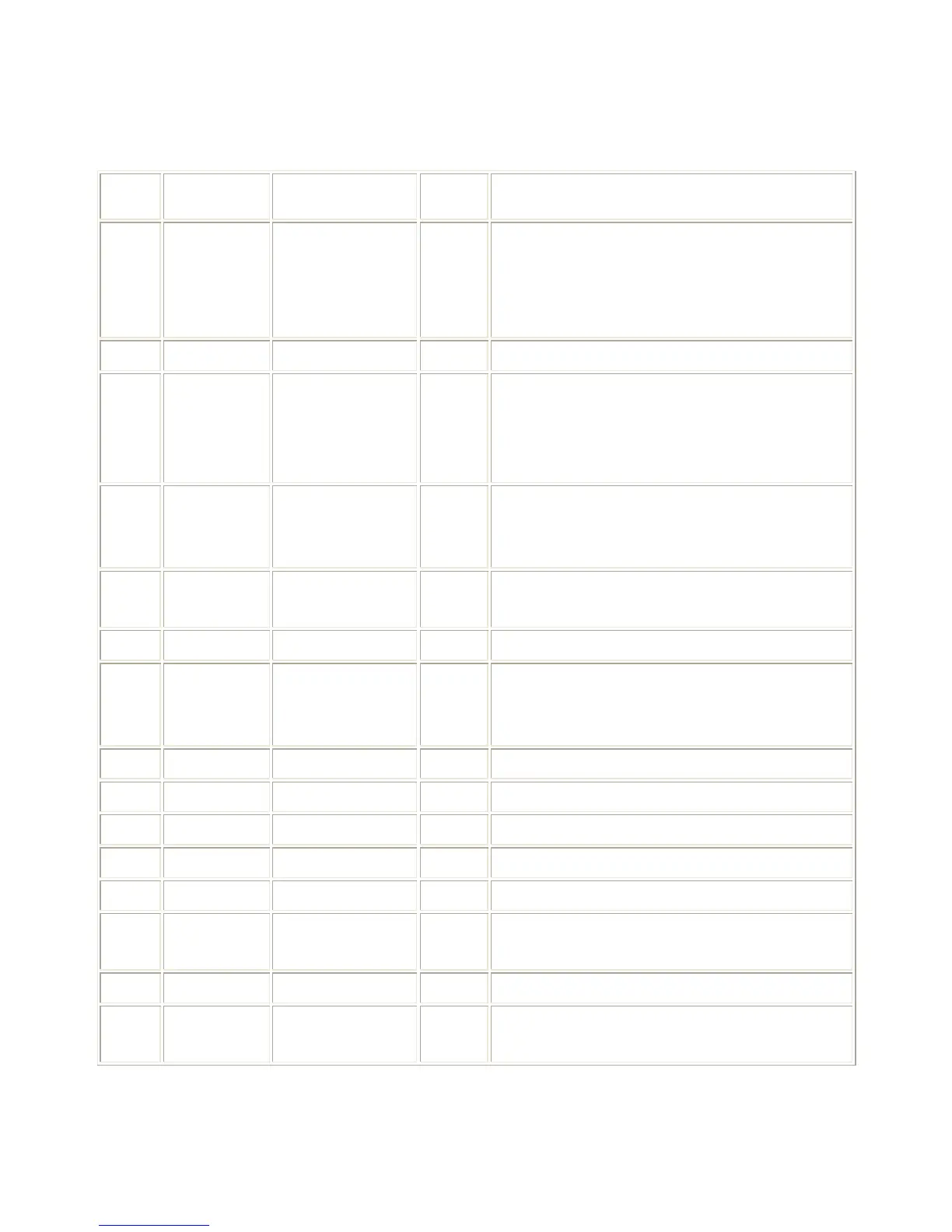
The pin assignments for nibble mode parallel interface connector is as following:
Table 3. Pin Assignments For nibble mode Parallel Interface Connector
A low on this line indicates that there are valid
data at the host. When this pin is de-asserted, the
+ve clock edge should be used to shift the data
into the device.
Data Bus. Single-directional.
A low on this line indicates that there are valid
data at the Device. When this pin is de-asserted,
the +ve clock edge should be used to shift the
data into the host.
When in reverse direction, a high indicates data,
while a low indicates a command cycle. In forward
direction, it functions as PtrBusy.
When low, device acknowledges reverse request.
When in forward direction, a high indicates data,
while a low indicates a command cycle. In reverse
direction, it functions as HostBusy.
A low indicates data in reverse direction
A low set by the device indicates that the reverse
data is available
A high indicates that host is in 1284 transfer
mode. Taken low to terminate.