EasyManuals Logo

Vacon 100 flow Installation Manual

Vacon 100 flow
128 pages
To Next Page IconTo Next Page
To Previous Page IconTo Previous Page
Page #62 background imageLoading...
Page #62 background image
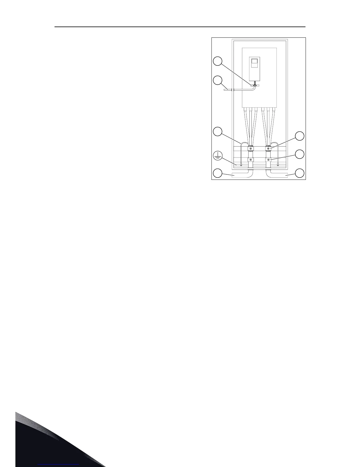
4 Connect the cables. The picture shows an example
of good cabling.
a)
Connect the phase conductors of the mains
cable and of the motor cable into the correct
terminals. If you use a brake resistor cable,
connect its conductors into the correct
terminals.
b)
Attach the grounding conductor of each cable
to a grounding terminal with a grounding
clamp for grounding conductor.
c)
Make sure that the external grounding
conductor is connected to the grounding bar.
See chapter 2.4 Grounding and earth fault
protection.
d)
See the correct tightening torques in Table 24.
L1 L2 L3 U V W
B
A
C
E
F
G
D
A. The mains cables
B. The motor cables
C. The grounding conductor
D. Pull relief
E. The grounding clamp for cable
shield, 360° grounding
F. The control cable
G. The grounding bar of the
control cable
VACON · 62 POWER CABLING
6
LOCAL CONTACTS: HTTP://DRIVES.DANFOSS.COM/DANFOSS-DRIVES/LOCAL-CONTACTS/

Table of Contents

Other manuals for Vacon 100 flow

Questions and Answers:

Question and Answer IconNeed help?

Do you have a question about the Vacon 100 flow and is the answer not in the manual?

Vacon 100 flow Specifications

General IconGeneral
Protection classIP20
Communication interfaceRS-485
Operating temperature-10°C to +50°C
Storage temperature-40°C to +70°C
Ambient temperature-10°C to +40°C
Control methodSensorless vector control
Communication protocolsCANopen
ApprovalsCE, UL
I/O2 analog inputs
Protection featuresOvercurrent, overvoltage, undervoltage, overtemperature
Frequency range0 Hz to 400 Hz
Humidity5% to 95%, non-condensing
Voltage range208-240 V

Related product manuals