EasyManuals Logo

Vacon 100 flow Installation Manual

Vacon 100 flow
128 pages
To Next Page IconTo Next Page
To Previous Page IconTo Previous Page
Page #63 background imageLoading...
Page #63 background image
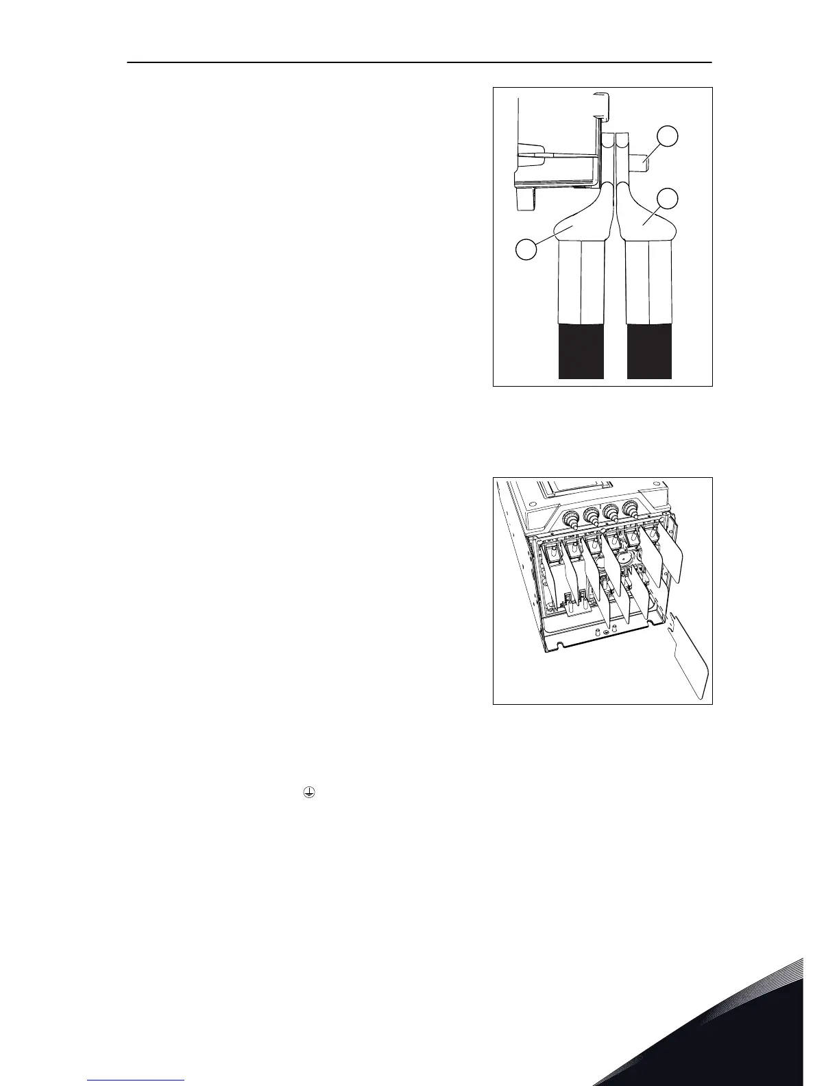
5 If you use many cables on one connector, put the
cable lugs on top of each other.
A
C
B
A. The first cable lug
B. The second cable lug
C. The connector
6 If you use thick cables, put the cable insulators in
between the terminals to prevent contact between
the cables.
7 For MR9, attach the cover of the drive (unless you
want to make the control connections first).
8 Make sure that the grounding conductor is
connected to the motor and also to the terminals
that are identified with
.
a)
To obey the requirements of the standard
EN61800-5-1, obey the instructions in chapter
2.4 Grounding and earth fault protection.
b)
Connect the protective conductor to 1 of the
screw connectors with a cable shoe and an M8
screw.
POWER CABLING VACON · 63
LOCAL CONTACTS: HTTP://DRIVES.DANFOSS.COM/DANFOSS-DRIVES/LOCAL-CONTACTS/
6

Table of Contents

Other manuals for Vacon 100 flow

Questions and Answers:

Question and Answer IconNeed help?

Do you have a question about the Vacon 100 flow and is the answer not in the manual?

Vacon 100 flow Specifications

General IconGeneral
Protection classIP20
Communication interfaceRS-485
Operating temperature-10°C to +50°C
Storage temperature-40°C to +70°C
Ambient temperature-10°C to +40°C
Control methodSensorless vector control
Communication protocolsCANopen
ApprovalsCE, UL
I/O2 analog inputs
Protection featuresOvercurrent, overvoltage, undervoltage, overtemperature
Frequency range0 Hz to 400 Hz
Humidity5% to 95%, non-condensing
Voltage range208-240 V

Related product manuals