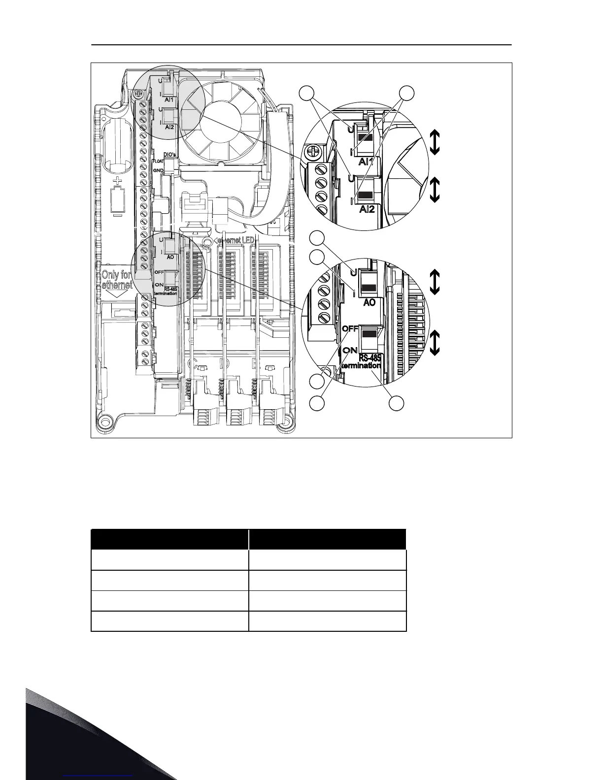
Fig. 29: The selections of the DIP switches
A. The voltage signal (U), 0-10 V input
B. The current signal (I), 0-20 mA input
C. OFF
D. ON
E. The RS-485 bus termination
Table 29: The default positions of the DIP switches
The DIP switch The default position
AI1 U
AI2 I
AO1 I
RS485 bus termination OFF
VACON · 78 CONTROL UNIT
7
LOCAL CONTACTS: HTTP://DRIVES.DANFOSS.COM/DANFOSS-DRIVES/LOCAL-CONTACTS/
 Loading...


