EasyManuals Logo

Vacon 100 flow Installation Manual

Vacon 100 flow
128 pages
To Next Page IconTo Next Page
To Previous Page IconTo Previous Page
Page #83 background imageLoading...
Page #83 background image
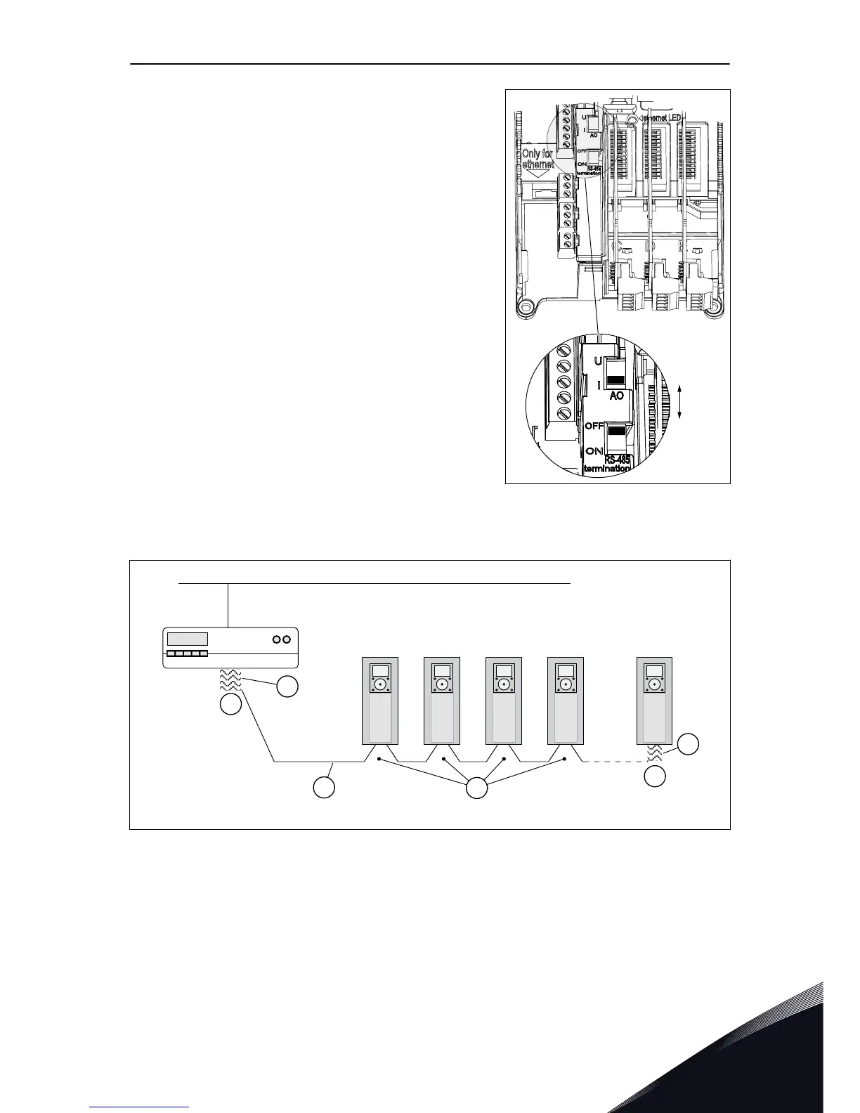
4 If the drive is the last device on the fieldbus line, set
the bus termination.
a)
Find the DIP switches on the left side of the
control unit of the drive.
b)
Set the DIP switch of the RS485 bus
termination to the ON position.
c)
Biasing is built in the bus termination resistor.
The termination resistance is 220 Ω.
5 Set the bus termination for the first and the last
device of the fieldbus line. We recommend that the
first device on the fieldbus is the master device.
D
D
E
A
C
B
A. The termination is activated
B. The termination is deactivated
C. The termination is activated with a DIP
switch
D. The bus termination. The resistance is
220 Ω.
E. The fieldbus
CONTROL UNIT VACON · 83
LOCAL CONTACTS: HTTP://DRIVES.DANFOSS.COM/DANFOSS-DRIVES/LOCAL-CONTACTS/
7

Table of Contents

Other manuals for Vacon 100 flow

Questions and Answers:

Question and Answer IconNeed help?

Do you have a question about the Vacon 100 flow and is the answer not in the manual?

Vacon 100 flow Specifications

General IconGeneral
Protection classIP20
Communication interfaceRS-485
Operating temperature-10°C to +50°C
Storage temperature-40°C to +70°C
Ambient temperature-10°C to +40°C
Control methodSensorless vector control
Communication protocolsCANopen
ApprovalsCE, UL
I/O2 analog inputs
Protection featuresOvercurrent, overvoltage, undervoltage, overtemperature
Frequency range0 Hz to 400 Hz
Humidity5% to 95%, non-condensing
Voltage range208-240 V

Related product manuals