EasyManuals Logo

Vacon 100 flow Installation Manual

Vacon 100 flow
128 pages
To Next Page IconTo Next Page
To Previous Page IconTo Previous Page
Page #99 background imageLoading...
Page #99 background image
REPLACING THE MAIN FAN ASSEMBLY, MR10 AND MR12
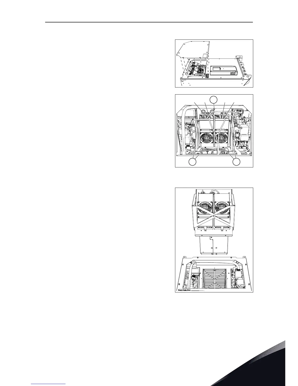
1 Loosen the 8 screws and lift off the service lid.
2 Disconnect the cables from each fan power supply.
a)
Disconnect the fan driver cable from connector
X61.
b)
Disconnect the DC supply cable from connector
X8.
Remove the 5 screws.
X61 X8 X61 X8
A
A A
A. The 5 screws
3 Pull out the whole fan assembly. The assembly
weighs approximately 11 kg.
4 Replace the main fan assembly. Attach it with the
screws.
5 Connect the cables and attach the service lid.
COMMISSIONING AND ADDITIONAL INSTRUCTIONS VACON · 99
LOCAL CONTACTS: HTTP://DRIVES.DANFOSS.COM/DANFOSS-DRIVES/LOCAL-CONTACTS/
8

Table of Contents

Other manuals for Vacon 100 flow

Questions and Answers:

Question and Answer IconNeed help?

Do you have a question about the Vacon 100 flow and is the answer not in the manual?

Vacon 100 flow Specifications

General IconGeneral
Protection classIP20
Communication interfaceRS-485
Operating temperature-10°C to +50°C
Storage temperature-40°C to +70°C
Ambient temperature-10°C to +40°C
Control methodSensorless vector control
Communication protocolsCANopen
ApprovalsCE, UL
I/O2 analog inputs
Protection featuresOvercurrent, overvoltage, undervoltage, overtemperature
Frequency range0 Hz to 400 Hz
Humidity5% to 95%, non-condensing
Voltage range208-240 V

Related product manuals