D1 (A) / D2 (B) – Status LEDs
▪ Powered Up: All LEDs OFF
▪ Initialization: LED A ON at start if initialization
▪ Runtime: LED A heartbeat and on-line status after successful initialization
Offline: 1 Hz (20% ON)
Online – Unencrypted: 1 Hz (80% ON)
Online – Encrypted: 3X 0.1s ON, 0.1s OFF followed by 0.1s ON, 0.3s OFF
▪ Waiting for Firmware Download: LED A = 0.1s ON, 0.1s OFF
▪ Communication Status: LED B indicates RS485 communications activity.
Connecting to bright blue
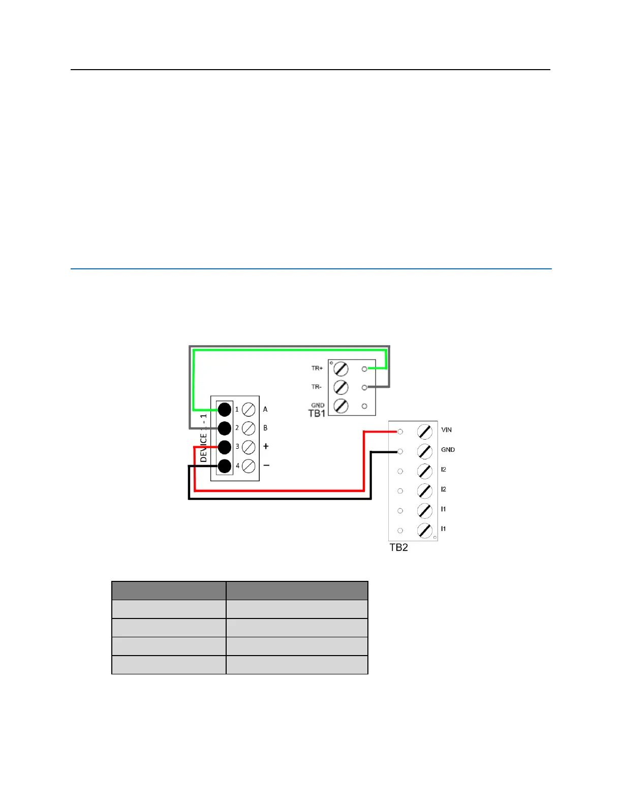
Communication between the bright blue controller and a VRI-1S3 reader interface is via RS-485 protocol. Any
one of the Device connectors (Device 1-1 through 2-16) on the bright blue controller can be used to
communicate with TB1 for RS-485 communications and TB2 for power on a VRI-1S3. The example below shows
connections between Device 1-1 on the bright blue controller and TB1, TB2 on the VRI-1S3.
Data Communication between bright blue and VRI-1S3