S1 –Addressing
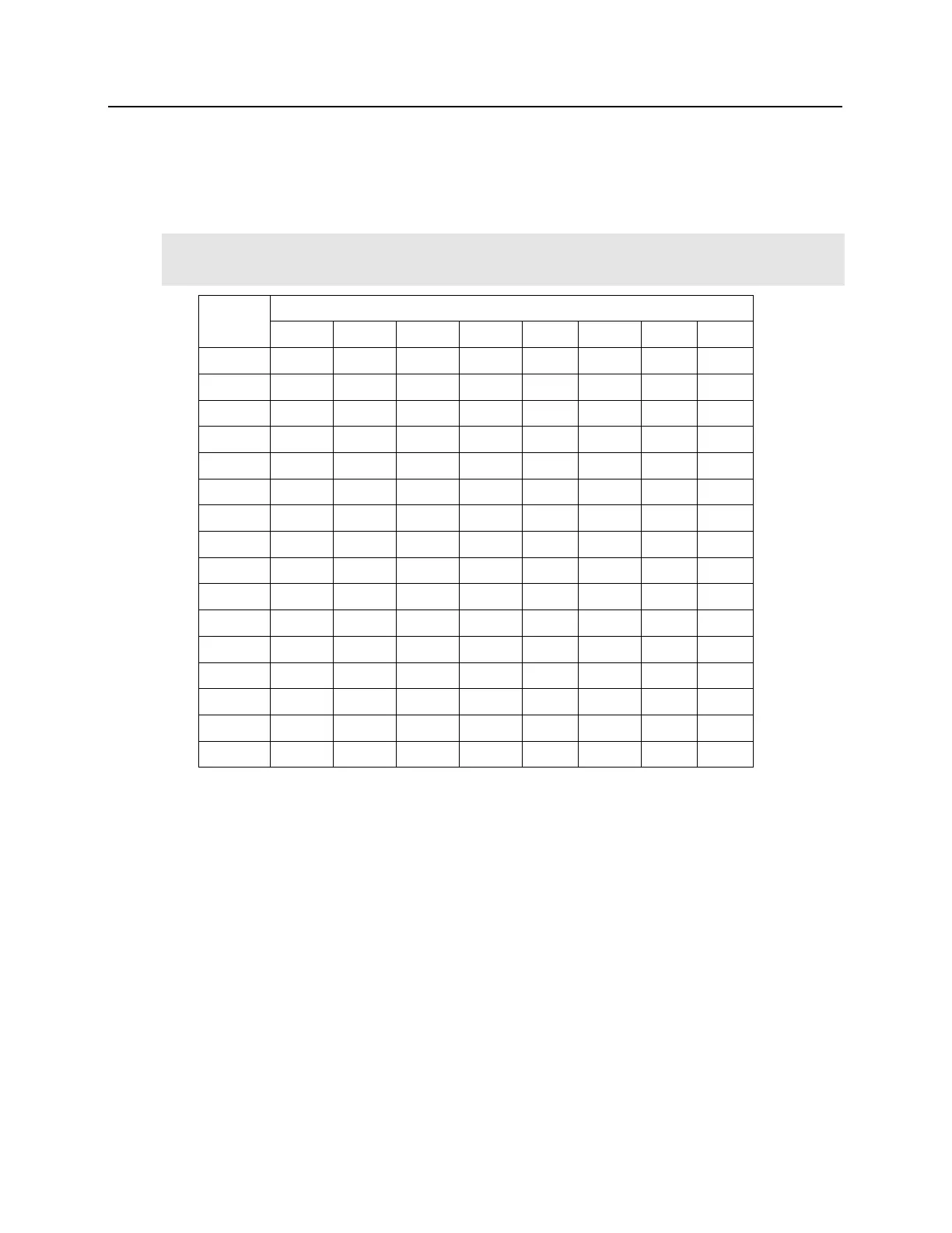
The address of the VRI-2 is dependent on the position of the DIP switches in S1.
The hardware address for each physical VRI-2 must be set to address 1 – 16 for use with bright blue.
The first reader is assigned “A” and the second reader is assigned “B”
(i.e. 1A & 1B or 5A & 5B)
.
S1 DIP Switch 6 & 7 determine RS-485 communications baud rate: default = 38,400
S1 DIP Switch 8 determines RS-485 encryption: default = OFF
A – R2 Status LEDs
▪ Powered Up: All LEDs OFF
▪ Initialization: LEDs A – R2 Sequenced ON then OFF at completion of initialization
▪ Runtime: LED A heartbeat and on-line status after successful initialization
Offline: 1 Hz (20% ON)
Online – Unencrypted: 1 Hz (80% on)
Online – Encrypted: 3X 0.1s ON, 0.1s OFF followed by 0.1s ON, 0.3s OFF
▪ Waiting for Firmware Download: LED A = 0.1s ON, 0.1s OFF
▪ Communication Status: LED B indicates RS485 communications activity
▪ LED 1: IN1 Status


 To Next Page