Wiring Instructions
The PIM400 can be powered directly from any data channel of the bright blue controller that is supplying 12 to
24 VDC or separately from a local power supply. bright blue and the PIM400 communicate via RS-485 protocol.
Wiring between bright blue and PIM400
The PIM400 can receive power and data from channels 1-1 through 2-16 of bright blue as long as the channel it
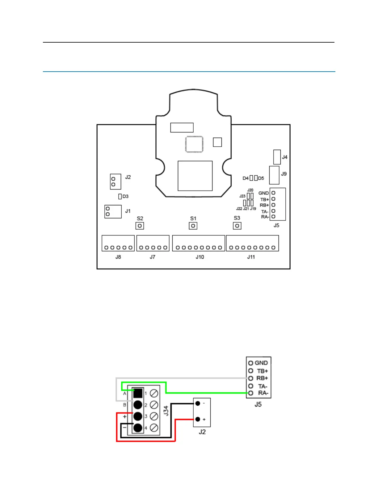
is connected to is receiving 12 to 24VDC. The PIM receives power at J2 and data at J5. J5 has two pins for Data
A and two pins for Data B. A jumper must be at J20 to combine the Data A pins and at J19 to combine the Data B
pins. The below example is using J34 on the bright blue board to J5 and J2 on the PIM400.