EasyManuals Logo
Home>Vanderbilt>Security Sensors>bright blue

Vanderbilt bright blue User Manual

Vanderbilt bright blue
242 pages
To Next Page IconTo Next Page
To Previous Page IconTo Previous Page
Page #212 background imageLoading...
Page #212 background image
VBBIM09/33/20 v5.0.3
Chapter 15 Schlage Wireless Readers 211
All Schlage wireless devices should be powered with a 12VDC power supply. The PIM-SBB (Legacy) can be
powered directly from any data channel of the bright blue controller that is supplying 12VDC or separately from a
local power supply. bright blue and the PIM-SBB communicate via RS-485 protocol.
Wiring between bright blue and PIM Module
The PIM can receive power and data from channels 1-1 through 2-16 of bright blue as long as the channel it is
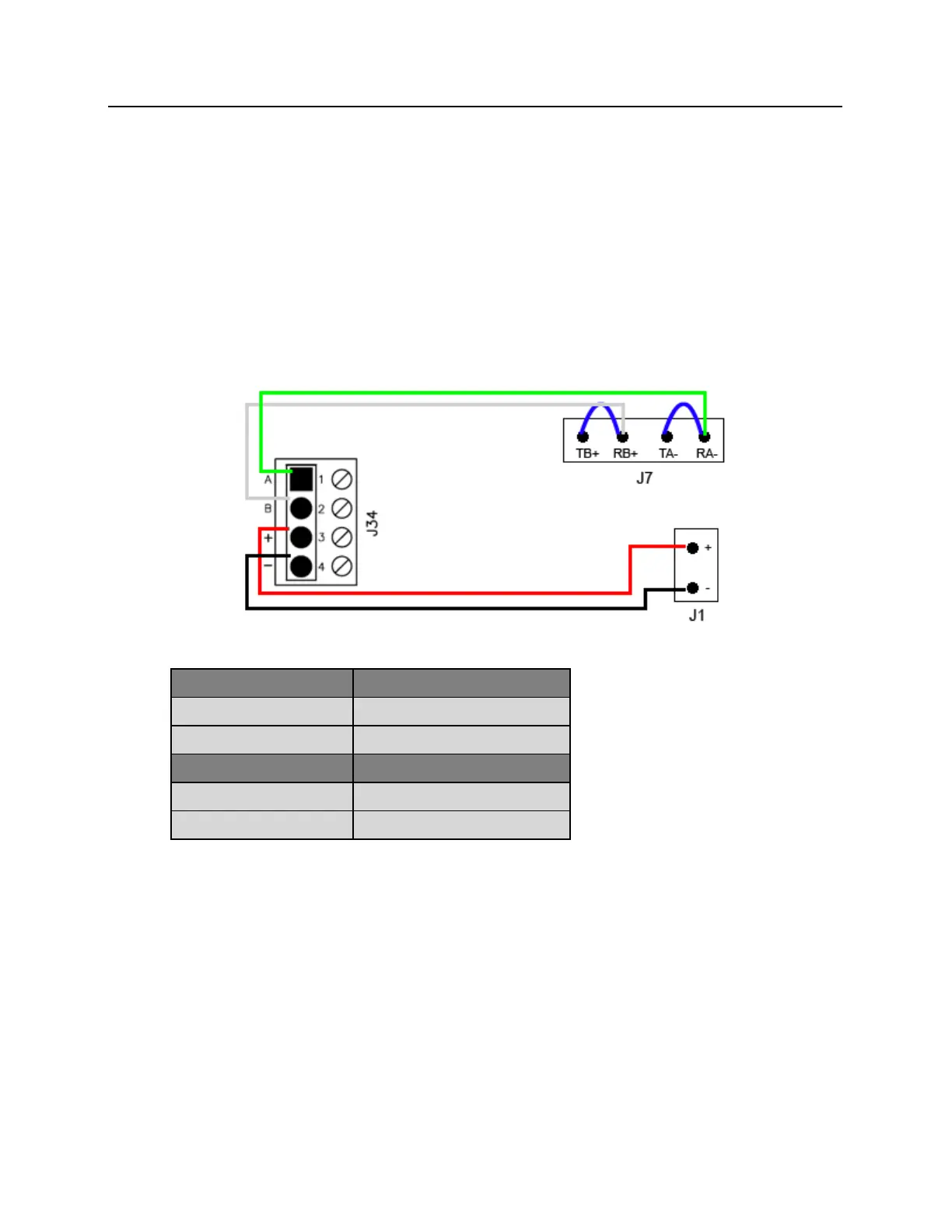
connected to is receiving 12VDC. The PIM receives power at J1 and data at J7. J7 has two pins for Data A and
two pins for Data B. The Data A pins (TA- and RA-) must be jumpered together. The Data B pins (TB+ and RB+)
must also be jumpered together. The example below shows using Device 1-1 on the bright blue board to J7 and
J1 on the PIM.
Data Communication and Power between bright blue and PIM-SBB
bright blue
PIM-SBB J7
Pin 1 - A (Data A)
TA- RA- (jumpered)
Pin 2 - B (Data B)
TB+ RB+ (jumpered)
bright blue
PIM-SBB J1
Pin 3 - + (Power)
Pin 1 - PWR (Power)
Pin 4 - - (Ground)
Pin 2 - GND (Ground)

Table of Contents

Questions and Answers:

Question and Answer IconNeed help?

Do you have a question about the Vanderbilt bright blue and is the answer not in the manual?

Vanderbilt bright blue Specifications

General IconGeneral
BrandVanderbilt
Modelbright blue
CategorySecurity Sensors
LanguageEnglish

Related product manuals