Optional - Powering VBB-RI Directly From a Power Supply
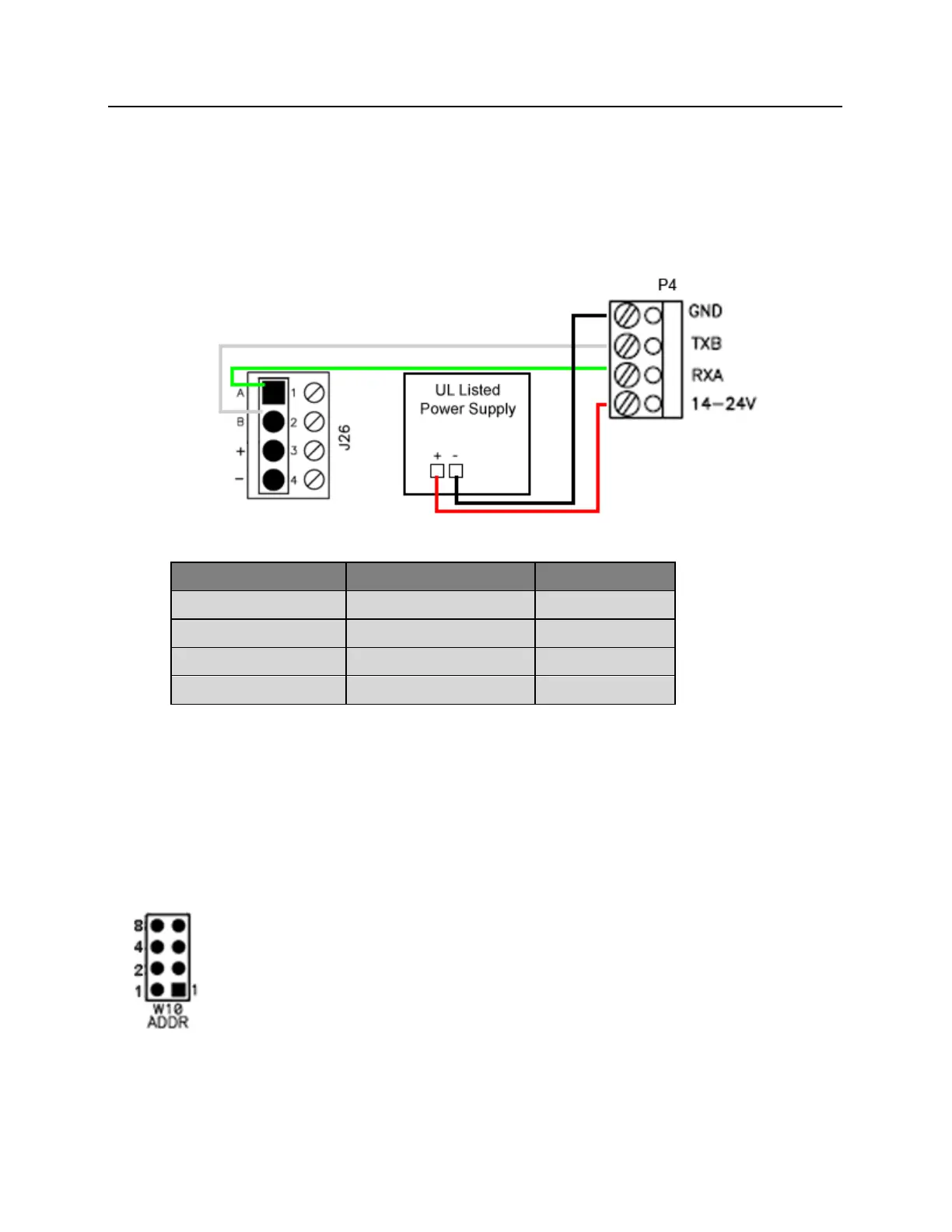
If desired, the VBB-RI can receive power directly from a UL 294 Listed Power Limited power supply. In that
situation communication between the bright blue controller and the VBB-RI is via RS-485 protocol. Any one of
the Device connectors (Device 1-1 through 2-16) on the bright blue controller can be used to communicate with
P4 on a VBB-RI. Power will be supplied independently from the power supply.
Data Communication between bright blue and VBB-RI
Addressing the VBB-RI
W10 on the VBB-RI consists of four jumpers that can be combined to set the address for the device. It is
recommended that the set address correspond to the slot on the bright blue controller it is connected to. For
example, if the VBB-RI is connected to the bright blue controller at Device 1-15 (Channel 1, Address 15) then
the jumpers on the VBB-RI should equal 15. If the VBB-RI is connected to Device 2-7 (Channel 2 Address 7) then
the jumpers should equal 7.
Make a note of the address of the VBB-RI and which channel it is connected to. This information will be required to
set up the lock in the software.